background image

2-29

1V

A

Pin 5 of PK5
or TP49

20

µ

s

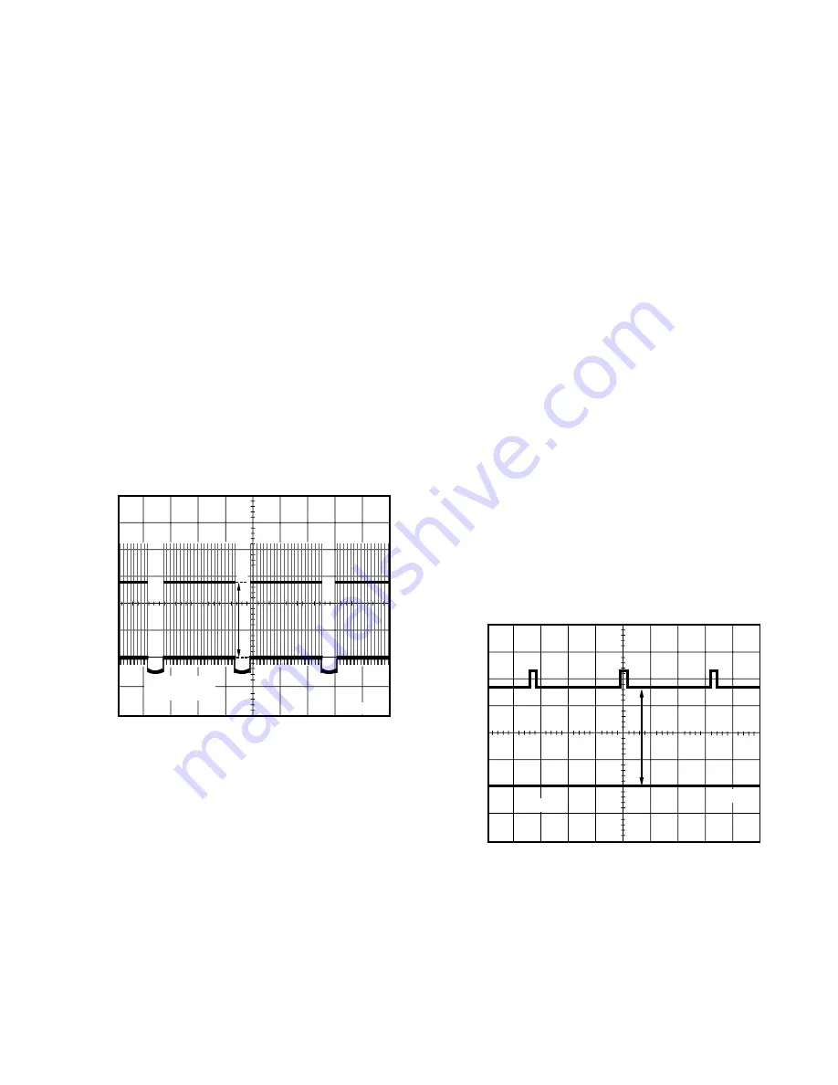
SUB CONTRAST ADJUSTMENT

Purpose:

To set the optimum sub contrast level.

Symptom of Misadjustment:

The picture is too dark or too light.

Test Point

: Pin 5 of PK5 (TV Main C.B.A.)

or TP49 (CRT C.B.A.)

Adjustment : SUB CONTRAST (EVR)
Specification: 2.8 +/- 0.1Vp-p
Input

: Video Input Jack

Crosshatch Pattern Signal  1Vp-p
(75 ohm terminated)

Mode

: STOP

Equipment

: Oscilloscope, NTSC Video Pattern Generator

1. Supply a Crosshatch Pattern Signal to the Video Input

Jack.

2. Connect the Oscilloscope to Pin 5 of PK5 on the TV Main

C.B.A. or TP49 on the CRT C.B.A.

3. Select SUB BRIGHT in EVR adjustment mode. Then, after

making a note of the original value, adjust to the minimum
(C0).

4. Select SUB CONTRAST in EVR adjustment mode and

adjust so that the level A is 2.8 +/- 0.1Vp-p.

5. Select SUB BRIGHT in EVR adjustment mode and reset to

the original value.

Fig. E6

50V

5ms

A

TP50

DC GND

FOCUS, SCREEN, CUT OFF, DRIVE
ADJUSTMENT

Purpose:

To set the optimum Focus and Screen.

Symptom of Misadjustment:

The picture is out of Focus and there will be an improper
screen color mix.

Test Point

: TP50 (CRT C.B.A.)

Adjustment : FOCUS CONTROL (Flyback Transformer),

SCREEN CONTROL (Flyback Transformer),
SUB BRIGHT (EVR),
B DRIVE (EVR),
R DRIVE (EVR),
B CUT -OFF (EVR),
G CUT -OFF (EVR),
R CUT -OFF (EVR)

Specification: Refer to descriptions below.
Input

: Video Input Jack

Monoscope Pattern Signal

Mode

: STOP

Equipment

: Oscilloscope, NTSC Video Pattern Generator

1. Supply a Monoscope Pattern Signal to the Video Input

Jack.

2. Connect the Oscilloscope to TP50 on the CRT C.B.A.

(Use TP47E for GND.)

3. Select SUB BRIGHT and move the shaded area to the

value in EVR adjustment mode.

4. Adjust the FOCUS CONTROL on the Flyback Transformer

so that the center of picture is the sharpest.

5. Press DISPLAY key (Service Switch) on the remote control

for collapse scan. (Refer to How to Enter Service Mode.)

6. Turn the SCREEN CONTROL on the Flyback Transformer

fully counterclockwise.

7. Adjust SUB BRIGHT in EVR adjustment mode so that the

level A is 185 +/- 5VDC.

Fig. E7

8. Turn the SCREEN CONTROL on the Flyback Transformer

clockwise carefully and stop at the point where any color is
first observed.

9. In EVR adjustment mode, select the two colors not observed

in step 8 from the following control functions (B CUT -OFF,
G CUT -OFF, or R CUT -OFF) and adjust so that the
horizontal line becomes white.
For example, if the horizontal line appeared red in step 8,
select and adjust the B CUT -OFF and  G CUT -OFF.

Summary of Contents for PV-M2738 Operating

Page 1: ...LP SLP more than 40 dB Hi Fi Stereo SP LP SLP more than 60 dB Wow and Flutter Normal Mono SP Less than 0 2 WRMS LP Less than 0 3 WRMS SLP Less than 0 4 WRMS Hi Fi Stereo Less than 0 015 WRMS Broadcast...

Page 2: ...Power Supply Signal Process OSD Audio Amp System Control Servo TV Y C Process C B A 4 2 Junction C B A 4 4 TV Main C B A 4 6 CRT C B A 4 8 Head Amp C B A 4 8 TV Stereo C B A 4 9 Hi Fi Audio C B A 4 9...

Page 3: ...handling the tube 8 After servicing make the following leakage current checks to prevent the customer from being exposed to shock hazards LEAKAGE CURRENT COLD CHECK 1 Unplug the AC cord and connect a...

Page 4: ...herwise harmless motion such as the brushing together of your clothes fabric or the lifting of your foot from a carpeted floor can generate static electricity ESD sufficient to damage an ES device NOT...

Page 5: ...gW 5 hf V Xf g e e g7 Y hf V 1f g e e f J Yhg V L e g e e fW Y hg V Xe g e e e W Y V X g e eW Y V X g e W Y V X g e L W Y V O2 K H V hO2 0M I4 6K 5 V I4 6K g Y V X I4 6K Y V X I4 Y V X W Y V K O Y V...

Page 6: ...e f 0Y 3T5 J X e hV Y Y V4 e e h X T26T2 W26X e h 1 B 7 B1 e h e h X C 3 C5 e h R40R40R4 V40Y e e e e e e e e e e e e e e e e e e e e e e e e e e e e e e e e L J e 3 K O 5 e V4 0Y e Blank Tape No Vid...

Page 7: ...7 B1 h W Y e h e e h e h T C5 3 C5 heI40M e h R MI40Y V40Y e e 6X W e heW T2 g 6KO2 e 1 7 e he MI g X e e heS U h X N H e T e he g S J L e R R e heV Y f R MI4 e e e e e e e e e e e e e e e e e e e e e...

Page 8: ...g e J V 5eW Yhf O2 6K V 1e W 1e g e 7 X H W Y heW2 W 6X hfN L 3 Y L g e V 5 7 Yhf7 M 3 I 1 hf 31 N W 1 g eJ H J H he J HeJ N e N Lhf N 3 Y L g e7 5e75hf 75 e75 f31 N W 1 g e He Hhf f H L e e3 Y g 5 e...

Page 9: ...button on the remote control and try the button again 2 Cable Box Universal Remote Control Operation 2 The clock is set VCR Plus Setup is complete Before you begin make sure The Remote Control may be...

Page 10: ...D 0 1 2 3 4 4 Explanation of Codes Code No SERVICE MODE 2192 TV Screen Fault Code Cassette Down SW and S Tab SW Data Take Up Photo and Supply Photo Sensor Data Present mechanism position code Lock cod...

Page 11: ...n does not require the use of Exten sion Cables However for more extensive servicing Exten sion Cables should be used 1 Basic Service Position Service Position 1 1 Remove Rear Cover VCR Unit TV Power...

Page 12: ...ing Coil Connector CAUTION HOT CIRCUIT DO NOT touch Power circuit during service Stereo Amp C B A Insulated material 2 Service Position with Extension Cable Kit In Service Position with Extension Cabl...

Page 13: ...ow Wire 4 pin b 8 Pin Connector P6002 on the Main C B A c 14 Pin Connector P6201 on the Main C B A d Set Mode Select SW on the Mode Select SW Ass y to EJECT position and install onto Mechanism Chassis...

Page 14: ...turn this SW on Note To avoid damaging the connectors on Main C B A it is necessary to secure connectors with tape as shown 5 Set Mode Select SW on the Main C B A to Service Position 6 Plug the AC pl...

Page 15: ...d GND INSTALLATION OF VCR UNIT CAUTION 1 Swing the Cassette Door Lid all the way open until the Cassette Door tab clears the Opener Lever 2 Make sure that all guide tabs are aligned properly Then pres...

Page 16: ...otor Unit Fig 5 2 3 Remove the tape from the tape path 4 Rewind the tape into the cassette by rotating the Center Clutch Unit counterclockwise 5 Unhook Spring A of the Drive Rack Unit 6 Remove Screw A...

Page 17: ...ing 10 0VDC Power Supply again 5 After completing the removal procedure resolder Jumper J6004 Electrical Method Electrical method can only be performed when the mechanism is moved by rotating the Main...

Page 18: ...rs HOT circuit on TV Power C B A Anode Lead Degaussing Coil Connector Leads Heat Sink Plate Heat Sink Plate Deflection Yoke Connector Leads Speaker Connector Leads A V Jack C B A Leads After servicing...

Page 19: ...otect Combination VCR from being damaged by accidental shorting that may occur during servicing Also when troubleshooting the above type of Power Supply Circuit a variable isolation transformer is req...

Page 20: ...Layout Notes for mark Z Tweezers Solder Soldering Iron b Press the part downward with tweezers and solder both electrodes as shown below Fig 8 3 Note Do not glue the replacement leadless component to...

Page 21: ...they must not be reused Always use a new part when installing a chip part 1st 2nd 3rd B E C 1 CRT C B A 1 TV STEREO C B A or HI FI AUDIO C B A E B C LA7837 2SD1555LBMTV 2SD2499LBMA STR30130 2SC3063 AN...

Page 22: ...A 3 DISASSEMBLY ASSEMBLY PROCEDURES DISASSEMBLY ASSEMBLY PROCEDURES OF CABINET Disassembly Flowchart Perform all disassembly procedures in the order described in the DisassemblyFlowchart shownbelow W...

Page 23: ...e clamper 7 Model B C Disconnect Connector P4207 on the Hi Fi Audio C B A and remove the leads from the clampers 8 Disconnect 2 Connectors P805 and P806 on the TV Power C B A and remove the leads from...

Page 24: ...Locking Tabs B Note Work carefully so as not to break the Locking Tabs Fig D6 3 TV Power C B A Locking Tabs A Screw C Heat Sink Support Angle Sub Frame Screws B 3 TV Power C B A Tabs C Degaussing Coi...

Page 25: ...per Top Shield Plate Ass y TV Main C B A 6 Stereo Amp C B A Screws D Screw E Ground Wires Clampers Clampers B 7 Top Shield Plate Ass y Top Shield Plate Ass y Disassembly Procedure 1 Release 2 Clampers...

Page 26: ...in Disassembly Assembly Procedures of Mechanism Frame Screw H A B 9 VCR Chassis Unit Locking Tab E Locking Tab D Screws G Cassette Up Ass y Screw I Screw H Holder Unit Locking Tab F Alignment Project...

Page 27: ...cking Tab G Then lift it up and remove Fig D12 Reassembly Notes Installation of Cassette Up Ass y 1 Confirm that the 3 pins and Locking Tab G under the Cassette Up Ass y are in each of the 4 Guide Hol...

Page 28: ...r A Step Loc No Order of steps in procedure Part Part to be removed or installed Prior Step s Steps to be completed prior to the current step Disassembly Method This chart indicates Step Location No o...

Page 29: ...ottom side of the mechanism chassis Main Lever Through Hole Line Up T Loading Arm Unit S Loading Arm Unit Main Cam Gear Drive Rack Arm Through Holes Through Hole Through Hole Main Lever Drive Arm Load...

Page 30: ...tallation of Cylinder Unit 1 Install the Cylinder Unit so that the 2 holes on the lower surface of the Cylinder Unit fit over the 2 Guide Pins on the Cylinder Base and loosely secure it with 3 Screws...

Page 31: ...lity Adjustment procedures Opener Piece Pinch Arm Unit Motor Block Ass y and Audio Control Head Unit Disassembly Procedure 1 Remove the Opener Piece by pulling it upward while releasing 2 Locking Tabs...

Page 32: ...sis Through hole A as shown 3 Install the Main Cam Gear so that the 2 holes B marked E arealignedwiththeholeonchassis Through hole B as shown E indicates the EJECT position Fig J5 3 2 Holes on Main Ca...

Page 33: ...oles 2 Turn the P5 Arm Unit to the Capstan Rotor Unit Shaft side 3 Turn the T Brake Unit to the T Reel Table side 4 Position the Main Lever so that the Loading Rack Unit Pin fits in the niche of Main...

Page 34: ...distinguish between S Reel Table and T Reel Table Fig J8 2 2 Cut Washer A is not reusable Install a new one FullEraseHead TensionArmUnit SSpring Arm and S Reel Table Disassembly Procedure 1 Turn the F...

Page 35: ...r Unit Capstan Holder Unit and SS Brake Arm Unit Disassembly Procedure 1 Remove the Capstan Belt 2 Cut the Stopper with a cutter to remove 3 Pull up on the Capstan Rotor Unit 4 Remove 3 Screws B Then...

Page 36: ...as a replacement part Capstan Rotor Unit Capstan Holder Unit and Stopper are not reusable Install all new parts BecauseeveninvisiblescratchesontheCapstanRotor Unit shaft and the Capstan Holder Unit m...

Page 37: ...Notes 1 Installation of Center Clutch Unit 1 Fit the Center Clutch Unit into the Changing Gear as shown Fig J14 2 2 Cut Washer B is not reusable Install a new one Center Clutch Unit Changing Gear T Lo...

Page 38: ...ove Top Plate by releasing 2 Locking Tabs A on the left side and 2 Locking Tabs B on the right side of the Top Plate 2 Remove Wiper Arm Unit by releasing 2 Locking Tabs C Then remove the Holder Unit F...

Page 39: ...r right as indicated by the arrow 2 Install the Wiper Arm Unit so that the hole on the Wiper Arm Unit is aligned with the hole on the Drive Rack Unit Fig K1 2 2 Installation of Holder Unit 1 Turn the...

Page 40: ...ate VFK0329 Post Adjustment Driver VFK1301 Silicon Grease VUZS0002 Extension Cable Kit VFK27 Head Cleaning Stick VFK0330 H Position Adjustment Driver VFKS0081 Grease Video Audio Color Bar Monoscope 6k...

Page 41: ...nch adjust the nut on the Tension Adjust Piece counterclockwise only so that there is a space of 1 mm between the left edge of the P1 Post and the right edge of the Tension Post Make sure that the cen...

Page 42: ...on 25 2 5g 1 Play back a T120 cassette tape from the beginning for approx 10 to 20 seconds to stabilize tape movement 2 InsertaTensionMeterintotapepathandmeasuretheback tension 3 If the reading is out...

Page 43: ...an 15mVp p P2 AND P3 POST HEIGHT ADJUSTMENT PRELIMINARY ADJUSTMENT Purpose To properly align the position of the tape with the Cylinder Lead so that the tape runs with stability Symptom of Misadjustme...

Page 44: ...the tape and insert it again to access the Neutral Tracking position 4 Play back the alignment tape and confirm that the RF envelope appears 5 With Post Adjust Driver adjust P2 and P3 post height so t...

Page 45: ...Head Symptom of Misadjustment Ifthecontrolsignalisnotproperlypickedup Servo Operation cannot be achieved A Blue screen will be seen in Playback This confirmation is required when the Audio Control He...

Page 46: ...elope is at maximum 6 Before finding the center of the maximum period of the envelope rotatethefixturebackandforthslightlytoconfirm the limits on either side of the maximum period 7 Push the Tracking...

Page 47: ...4 Frequency Counter Frequency Range 0 to 150MHz 5 Plastic Tip Driver and Non Metal Driver 6 Isolation Transformer Variable 7 VHS Alignment Tape VFMS0003H6 8 White Pattern Generator HOW TO READ THE ADJ...

Page 48: ...inimum Model B C Adjust R4951 SEPARATION ADJ so that the signal level is minimum Fig E3 1 8 P4201 GND 4 pin FM VCO ADJUSTMENT Purpose To set VCO free run frequency Symptom of Misadjustment Even when s...

Page 49: ...2 Press DISPLAY key on the remote control for collapse scan Note Before pressing DISPLAY key on the remote control for collapse scan select the desired control function and move the shaded area to the...

Page 50: ...US CONTROL Flyback Transformer SCREEN CONTROL Flyback Transformer SUB BRIGHT EVR B DRIVE EVR R DRIVE EVR B CUT OFF EVR G CUT OFF EVR R CUT OFF EVR Specification Refer to descriptions below Input Video...

Page 51: ...Point Pin 5 of PK5 TV Main C B A or TP49 CRT C B A Adjustment SUB COLOR EVR SUB TINT EVR Specification C 1 50 0 15Vp p Input Video Input Jack Rainbow Color Bar Mode STOP Equipment Oscilloscope NTSC Vi...

Page 52: ...FOCUS CONTROL Flyback Transformer SCREEN CONTROL Flyback Transformer SUB BRIGHT EVR G DRIVE EVR B DRIVE EVR R CUT OFF EVR G CUT OFF EVR B CUT OFF EVR Specification Refer to descriptions below Input V...

Page 53: ...y a White Pattern Signal to the Video Input Jack 11 Press DISPLAY key on the remote control again to return for full frame scan 12 Select G DRIVE and B DRIVE in EVR adjustment mode and adjust so that...

Page 54: ...al Audio signal Service Test Point inhibit sensors defeat auto tracking function connect to 5V TP6009 5V Head SW Test Point Information Test Point with a Test Pin Test Point with a jumper wire across...

Page 55: ...ation II C B A Operation I C B A Component Side Component Side Component Side 1 5 PK5 PK2 5 pin CRT C B A TP50 TP47E TP49 Foil Side VOLUME UP VOLUME DOWN REW REVIEW PLAY REPEAT POWER FF CUE CH DOWN CH...

Page 56: ......

Page 57: ......

Page 58: ......

Page 59: ......

Page 60: ......

Page 61: ......

Page 62: ......

Page 63: ......

Page 64: ......

Page 65: ......

Page 66: ......

Page 67: ......

Page 68: ......

Page 69: ......

Page 70: ......

Page 71: ......

Page 72: ......

Page 73: ......

Page 74: ......

Page 75: ......

Page 76: ......

Page 77: ......

Page 78: ......

Page 79: ......

Page 80: ......

Page 81: ......

Page 82: ......

Page 83: ......

Page 84: ......

Page 85: ......

Page 86: ......

Page 87: ......

Page 88: ......

Page 89: ......

Page 90: ......

Page 91: ......

Page 92: ......

Page 93: ......

Page 94: ......

Page 95: ......

Page 96: ......

Page 97: ......

Page 98: ......

Page 99: ......

Page 100: ......

Page 101: ......

Page 102: ......

Page 103: ......

Page 104: ......

Page 105: ......

Page 106: ......

Page 107: ......

Page 108: ......

Page 109: ......

Page 110: ......

Page 111: ......

Page 112: ......

Page 113: ......

Page 114: ......

Page 115: ......

Page 116: ......

Page 117: ......

Page 118: ......

Page 119: ......

Page 120: ......

Page 121: ......

Page 122: ......

Page 123: ......

Page 124: ......

Page 125: ......

Page 126: ......

Page 127: ......

Page 128: ......

Page 129: ...s are replaced apply the recommended lubricants or adhesive for better maintenance of the unit Note Parts with no Ref No in EXPLODED VIEW are not supplied And some Ref No will be skipped Be sure to ma...

Page 130: ...r Unit Capstan Holder Unit and Stopper are supplied as a Capstan Rotor Kit only 2 Capstan Stator Unit Capstan Rotor Unit Capstan Holder Unit and Stopper are supplied as a Capstan Stator Kit only Howev...

Page 131: ...nt Availability Part Number Silicon Grease Available from Factory VFK1301 Spindle Oil Purchase from Local Supplier Grease Available from Factory VFKS0081 CASSETTE UP COMPARTMENT SECTION 69 4 As an ESD...

Page 132: ...AFETY NOTICE COMPONENTS IDENTIFIED BY THE SIGN HAVE SPECIAL CHARACTERISTICS IMPORTANT FOR SAFETY WHEN REPLACING ANY OF THESE COMPONENTS USE ONLY THE SPECIFIED PARTS CHASSIS FRAME SECTION 1 To A in Cha...

Page 133: ...MODULATOR UNIT has already been pre adjusted at the factory do not try to adjust the UHF VHF TUNER TV DEMODULATOR UNIT The UHF VHF TUNER TV DEMODULATOR UNIT replacement part is available as a complete...

Page 134: ...Infrared Remote Control Unit replacement part is available as a complete assembly unit only Do not try to disassemble the Infrared Remote Control Unit However the battery cover is available separatel...

Page 135: ...s already been pre adjusted at the factory do not try to adjust the UHF VHF TUNER TV DEMODULATOR UNIT The UHF VHF TUNER TV DEMODULATOR UNIT replacement part is available as a complete assembly unit on...

Page 136: ...qlm rpeflk ibcqIpqvolcl j S hbf NPP qmaVTOMRM _lqqlj rpeflk ibcqIpqvolcl j S hbf NPQ qmaVTOMQV _lqqlj rpeflk ofdeqIpqvolcl j S hbf NRP qjjTTQNO i jmbo R hbf NRQ qjjTTQNP i jmbo R hbf NTQ qruTTNNR eb q...

Page 137: ...ELECTRICAL REPLACEMENT PARTS LIST E1 E2 E4 E5 E6 E7 E9 E11 E12 E16 E17 E18 PRINTED CIRCUIT BOARD ASSEMBLY bN sbmpPMRMb j fk K_K K bKpKaK oqi hbf E F bN sbmpPMRMa j fk K_K K bKpKaK oqi hbf E _I F bO s...

Page 138: ...LNMt Nh oPMPU boapOqgOOO OKOh oPMPV bogSdbvgOTOs jdc efm NLNMt OKTh E F oPMQM bogSdbvgNMPs jdc efm NLNMt NMh E F oPMQO bogSdbvgNMPs jdc efm NLNMt NMh oPMQP bogSdbvgOOOs jdc efm NLNMt OKOh E F oPMQQ bo...

Page 139: ...oQMPP bogSdbvgUONs jdc efm NLNMt UOM oQMPQ bogSdbvgNMPs jdc efm NLNMt NMh E _I F oQMPS bogSdbvgPPPs jdc efm NLNMt PPh E _I F oQMPT boapOqgOOP OOh E _I F oQNMN bogSdbvgRSPs jdc efm NLNMt RSh oQNMO bog...

Page 140: ...pOqgOON OOM oSOMN bsk v MP_NR s of _ib NMMh E F bsjcSp MM_NR s of _ib NMMh E _I F oSOMO bogSdbvgNMQs jdc efm NLNMt NMMh oSOMP bogSdbvgPPPs jdc efm NLNMt PPh oSOMQ bogSdbvgNMOs jdc efm NLNMt Nh oSOMR b...

Page 141: ...Ms MKMN PMRQ b rsNeNMPwck efm HUMBJOMB RMs MKMN E _I F PMRR b rsNbNMQwck efm HUMBJOMB ORs MKN PMRS b rsN OOQwck efm HUMBJOMB NSs MKOO PMRT b rsNbNMQwck efm HUMBJOMB ORs MKN PMRU b rsNeNMPwck efm HUMBJ...

Page 142: ...s OO SOOO b rsNeOTOh_k efm RMs OTMMm SOOP b rsNeNMPh_k efm RMs MKMN SOOQ b b Mgh NMN bib qolivqf SKPs NMM SOOR bogSdbvMoMMs jdc efm NLNMt M SOOU s vp_o NMQju bo jf HJOMB NSs MKN SOPN b b N h NMM bib q...

Page 143: ...SdbvgQTPs jdc efm NLNMt QTh oVPNP bogSdbvgQTPs jdc efm NLNMt QTh oVPNQ bogSdbvgQTPs jdc efm NLNMt QTh oVPNS bogSdbvgQTPs jdc efm NLNMt QTh oVPNT bogSdbvgQTPs jdc efm NLNMt QTh oVPNU bogSdbvgPVPs jdc e...

Page 144: ...Mh hbf oVOMT bogSdbvgPPOs jdc efm NLNMt PKPh oVONN bogSdbvgQTOs jdc efm NLNMt QKTh CAPACITORS QOMN b n_NeQTPhc mlivbpqbo RMs MKMQT QOMO b n_NeQTPhc mlivbpqbo RMs MKMQT QOMP b b Mgh PPM bib qolivqf SKP...

Page 145: ...ptfq e ptSPMU bsnm aMRo mrpe ptfq e ptSPNM bsnm aMRo mrpe ptfq e ptSPNN bsnm aMRo mrpe ptfq e ptSPNO bsnm aMRo mrpe ptfq e MISCELLANEOUS bPS sjupMRTR iba pm bo AUDIO VIDEO JACK C B A A INTEGRATED CIRC...

Page 146: ...dbvgQTPs jdc efm NLNMt QTh oPRMO bogSdbvgRSMs jdc efm NLNMt RS oPRMP bogSdbvgRSMs jdc efm NLNMt RS oPRMQ bogSdbvgRSMs jdc efm NLNMt RS oPRMR bogSdbvgRSMs jdc efm NLNMt RS oPRMS bogSdbvgRSNs jdc efm NL...

Page 147: ...s vp_obQTPhu bo jf ORs MKMQT hbf E _I F QSMU b N jNMM_ bib qolivqf NSs NM QSMV b N jNMN_ bib qolivqf NSs NMM QSNM s vp_obQTPhu bo jf ORs MKMQT hbf QSNN b N jQTM_ bib qolivqf NSs QT QSNO b N jNMM_ bib...

Page 148: ...sobp OqhUOR plifa HJNMB NLOt UKOj lo sobp OqhUORq plifa HJNMB NLOt UKOj oTMMO boapOqgOTN OTM oTMPM boapOqgNUO NKUh oTMPN boapOqgNUO NKUh oTMPO boapOqgNUO NKUh CAPACITORS QMN b b NedbOoO bib qolivqf R...

Page 149: ...PHcNMp p obt tLt peboIpqbbi bQV uvkPHcUp p obt tLt peboIpqbbi bRN qg SPNV crpb eliabo bRO qr TTRQO c_q pefbia mi qbIpqbbi hbf bRP qjjNSQUMJN i jmbo bUM irpSPMMO pr_ eb q pfkh mi qbIpqbbi hbf TV MAIN C...

Page 150: ...i bV sbmpMQNOMdN raflLsfabl g h K_K K oqi bV sbmpMQNOUcN raflLsfabl g h K_K K oqi bNN sbmpQMNQc pqbobl jm K_K K oqi bNN sbmpQMNQd pqbobl jm K_K K oqi bNO iomOPMMV qs mltbo K_K K oqi bNS iojSNMMRa qs j...

Page 151: ...Printed in Japan...

Reviews: