1-13
Opener Lever
Cassette Door Tab
View "A"
Cassette Door-Lid
Cassette Door-Lid
VCR Unit
View "A"
Press
CAUTION
Portion "a"
Top Plate
Tab
Lever
Lever
Hole
Hole
Holder Unit
Tab
Slide
+
P2552
Unsolder
Chassis
Motor P.C.B. of
Motor Block Ass'y
Rear Side View
-
P2551
DC Power Supply
(+10VDC)
"a"
"c"
"b"
"a"
"b"
Load
Unload/Eject
Main Cam Gear
Needlenose Pliers
HOT CIRCUIT
Primary circuit exists on the Main C.B.A., TV Main C.B.A., and
TV Power C.B.A.
This circuit is identified as "HOT" on the C.B.A. and in the
Service Manual. Use extreme care to prevent accidental shock
when servicing.
SERVICE MODE
In order to inhibit detection of the Supply & Takeup Photo
Transistors, Reel Sensor, and Cylinder Lock, place a jumper
between TP6001 and GND.
In this mode, Mechanism movement can be confirmed. When
removing Cassette Up Ass'y, it can be confirmed without a
cassette.
To release from this mode, remove the jumper between
TP6001 and GND.
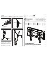
INSTALLATION OF VCR UNIT
CAUTION
1. Swing the Cassette Door -Lid all the way open until the
Cassette Door tab clears the Opener Lever.
2. Make sure that all guide tabs are aligned properly. Then,
press the VCR Unit straight in.
Fig. 3
METHOD FOR LOADING/
UNLOADING OF MECHANISM
(Manual Method)
Turn the Main Cam Gear counterclockwise (for loading) or
clockwise (for unloading) using needlenose pliers etc.
Note:
Do not use this method if Mechanism is jammed or locked.
Fig. 4-1
(Electrical Method)
Remove the solder as shown and apply +10.0 VDC Power
Supply (DC + to Portion "a," DC - to Portion "c").
Note:
Be careful not to let the DC Power Supply Unit GND contact
the chassis GND. This may damage the Loading Motor Drive
IC (IC 2501).
Be sure to apply DC + to Portion "a" of Motor P.C.B.
If DC + is applied to Portion "b", the Loading Motor Drive IC
(IC2501) may be damaged.
Fig. 4-2
Note:
Do not forget to solder Portions "a" and "b" after loading/
unloading operation is completed.
When loading without a cassette, press Portion "a" on
both sides of the Holder Unit of Cassette Up Ass'y so that
the Levers clear the Tabs and Holes.
Fig. 4-3
Summary of Contents for PV-M2738 Operating
Page 56: ......
Page 57: ......
Page 58: ......
Page 59: ......
Page 60: ......
Page 61: ......
Page 62: ......
Page 63: ......
Page 64: ......
Page 65: ......
Page 66: ......
Page 67: ......
Page 68: ......
Page 69: ......
Page 70: ......
Page 71: ......
Page 72: ......
Page 73: ......
Page 74: ......
Page 75: ......
Page 76: ......
Page 77: ......
Page 78: ......
Page 79: ......
Page 80: ......
Page 81: ......
Page 82: ......
Page 83: ......
Page 84: ......
Page 85: ......
Page 86: ......
Page 87: ......
Page 88: ......
Page 89: ......
Page 90: ......
Page 91: ......
Page 92: ......
Page 93: ......
Page 94: ......
Page 95: ......
Page 96: ......
Page 97: ......
Page 98: ......
Page 99: ......
Page 100: ......
Page 101: ......
Page 102: ......
Page 103: ......
Page 104: ......
Page 105: ......
Page 106: ......
Page 107: ......
Page 108: ......
Page 109: ......
Page 110: ......
Page 111: ......
Page 112: ......
Page 113: ......
Page 114: ......
Page 115: ......
Page 116: ......
Page 117: ......
Page 118: ......
Page 119: ......
Page 120: ......
Page 121: ......
Page 122: ......
Page 123: ......
Page 124: ......
Page 125: ......
Page 126: ......
Page 127: ......
Page 128: ......
Page 151: ...Printed in Japan...