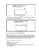
Fig. M6
4.1.3.4. POSITION ADJUSTMENT OF TENSION POST (PRELIMINARY)
Purpose :
To feed a constant tension to the tape so that the tape runs with stability, by
performing a preliminary adjustment.
Symptom of Misadjustment :
1) If the adjusted value is below the specification, the tape tension is not sufficient,
thus causing a tape slack to occur.
2) f the adjusted value is above the specification, the tape tension is too high, thus
causing tape damage to occur.
*Equipment Required :
2mm Hex. Wrench .................(Purchase Locally)
1. Remove the Cassette Up Ass'y.
2. Set the Service Mode.
3. Turn ON the Power Switch and press the Play Button to complete the loading
operation sequence.
4. As soon as loading is completed, insert the Hex. Wrench(2mm) into the Tension
Band Fastener and adjust it (only counterclockwise) as indicated by the arrow so
that the outside edge of the Tension Post lines up with the outside edge of Cut
Washer on the P1 post. (See Fig. M7)
5. Remove the Hex. Wrench (2mm).
6. Press the Stop/Eject Button to complete the unloading operation Sequence.
7. Reset the Service Mode.
8. Reinstall the Cassette Up Ass'y and cabinet parts.
58
Summary of Contents for PV-4601 A
Page 14: ...Fig 2 3 14 ...
Page 27: ...Fig 11 1 1 27 ...
Page 40: ...Fig D1 40 ...
Page 42: ...Fig D2 42 ...
Page 43: ...Fig D3 43 ...
Page 44: ...Fig D4 44 ...
Page 45: ...Fig D5 45 ...
Page 46: ...Fig D7 46 ...
Page 47: ...Fig D8 47 ...
Page 51: ...Fig M2 1 Fig M2 2 51 ...
Page 53: ...Fig M4 1 53 ...
Page 77: ...Fig M19 77 ...
Page 84: ...Fig J5 84 ...
Page 85: ...Fig J6 85 ...
Page 87: ...Fig J9 87 ...
Page 88: ...Fig J10 88 ...
Page 89: ...Fig J11 89 ...
Page 90: ...Fig J12 90 ...
Page 91: ...Fig J13 91 ...
Page 92: ...Fig J15 92 ...
Page 93: ...93 ...
Page 96: ...96 ...
Page 102: ...with the holes on the Pinch Lift Cam as shown in Fig A6 102 ...
Page 103: ...103 ...
Page 105: ...Fig K1 105 ...
Page 106: ...Fig K2 106 ...
Page 107: ...Fig K3 107 ...
Page 109: ...Fig B1 109 ...
Page 114: ...Fig E1 4 3 2 HOW TO READ THE ADJUSTMENT PROCEDURES 114 ...
Page 115: ...Fig E2 115 ...
Page 134: ...R6004 ERJ6GEYJ333V MGF CHIP 1 10W 33K 134 ...
Page 136: ...R6085 ERJ6GEYJ223V MGF CHIP 1 10W 22K 136 ...
Page 140: ...C4601 ECEA1CKA100 ELECTROLYTIC 16V 10 140 ...
Page 147: ...R6065 ERJ6GEYJ223V MGF CHIP 1 10W 22K 147 ...
Page 167: ...9 11 Operation Block Diagrams 1 167 ...
Page 178: ......
Page 204: ......
Page 205: ......


