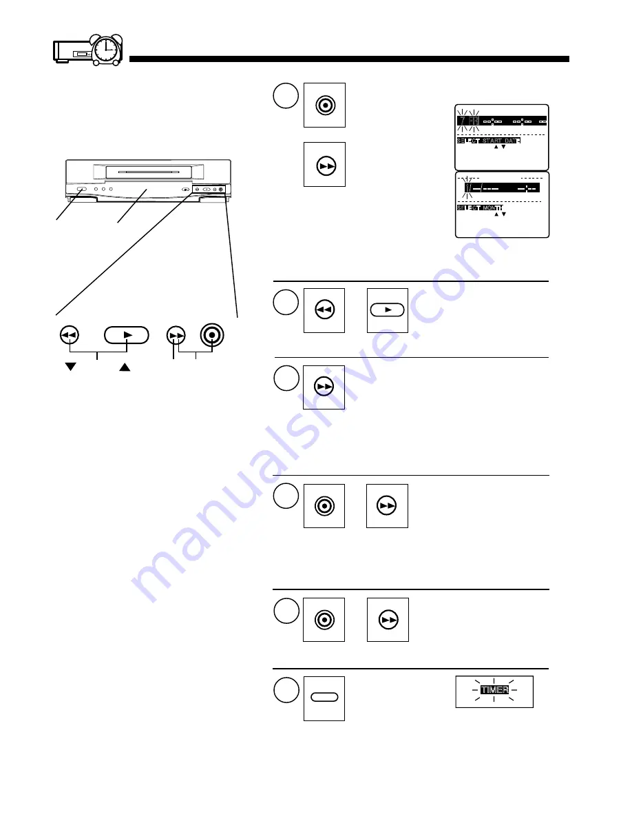
1
Hold down
REC/TIME.
KEY
TO END PUSH PROG KEY
BY SELECT /
SELE CT START DATE
7 FRI --:-- --:-- --
TODAY
DATE
START
STOP
CH
SLP
NEXT, PUSH SET KEY OR
2
or
3
4
(at the same time)
Push REC/TIME
and FF to display
program contents.
Items to be Set:
• recording DATE
• START time
• STOP time
• CH(annel), or LINE
• SPEED (SP, LP, SLP)
Push FF to set
and move on to
the next item.
and
SET CLOCK
NEXT, PUSH SET KEY OR
TO END PUSH PROG KEY
DST : ON
SELE CT MONTH
1 / -- / ---- --:--
KEY
BY SELECT /
6
• It is not possible to clear a timer program using the VCR
buttons. Please use the Remote Control.
• When recording programs via a cable box, make sure the
cable box is left on and tuned to the desired channel.
Push POWER off
to set the timer.
TIMER
Multi Function Display
(at the same time)
Push REC/TIME and
FF to exit this mode.
and
5
To set the next program,
repeat steps 2, 3, and 4 before continuing with step 5.
When the program is completed...
• Push SET (FF) repeatedly to
move to a particular item for
setting or correction.
Push FF to
enter the
program mode.
and
• If the clock is not set, pushing these
buttons will display the SET CLOCK
screen. In this case, proceed with
steps 2 and 3 to set the clock and then
steps 2~6 to set a timer recording.
• Once the VCR is in the Program mode, the PLAY, REC, FF,
and REW buttons on the VCR operate only as specified above.
Timer Recording Using VCR Buttons
A timer recording can be set up using the
buttons on the VCR. If necessary, the clock
can also be set.
SELECT
SET PROGRAM
(for up)
(for down)
Push REW or PLAY to
make your selection.
Multi
Function
Display
POWER
REW
PLAY
FF
REC/TIME
Summary of Contents for PV-4601 A
Page 14: ...Fig 2 3 14 ...
Page 27: ...Fig 11 1 1 27 ...
Page 40: ...Fig D1 40 ...
Page 42: ...Fig D2 42 ...
Page 43: ...Fig D3 43 ...
Page 44: ...Fig D4 44 ...
Page 45: ...Fig D5 45 ...
Page 46: ...Fig D7 46 ...
Page 47: ...Fig D8 47 ...
Page 51: ...Fig M2 1 Fig M2 2 51 ...
Page 53: ...Fig M4 1 53 ...
Page 77: ...Fig M19 77 ...
Page 84: ...Fig J5 84 ...
Page 85: ...Fig J6 85 ...
Page 87: ...Fig J9 87 ...
Page 88: ...Fig J10 88 ...
Page 89: ...Fig J11 89 ...
Page 90: ...Fig J12 90 ...
Page 91: ...Fig J13 91 ...
Page 92: ...Fig J15 92 ...
Page 93: ...93 ...
Page 96: ...96 ...
Page 102: ...with the holes on the Pinch Lift Cam as shown in Fig A6 102 ...
Page 103: ...103 ...
Page 105: ...Fig K1 105 ...
Page 106: ...Fig K2 106 ...
Page 107: ...Fig K3 107 ...
Page 109: ...Fig B1 109 ...
Page 114: ...Fig E1 4 3 2 HOW TO READ THE ADJUSTMENT PROCEDURES 114 ...
Page 115: ...Fig E2 115 ...
Page 134: ...R6004 ERJ6GEYJ333V MGF CHIP 1 10W 33K 134 ...
Page 136: ...R6085 ERJ6GEYJ223V MGF CHIP 1 10W 22K 136 ...
Page 140: ...C4601 ECEA1CKA100 ELECTROLYTIC 16V 10 140 ...
Page 147: ...R6065 ERJ6GEYJ223V MGF CHIP 1 10W 22K 147 ...
Page 167: ...9 11 Operation Block Diagrams 1 167 ...
Page 178: ......
Page 204: ......
Page 205: ......


