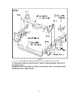
(ALIGNMENT 1)CASSETTE OPENER AND RACK Ass'y
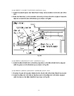
1. Install Cassette Opener into Side Plate R Ass'y slot and slide it to the far end of the
slot.
2. Slide the Rack Ass'y in the direction shown by arrow so that the nipple of Cassette
Opener is inside the slot of Rack Ass'y as shown in Fig B2.
Fig. B2
(ALIGNMENT 2)MAIN SHAFT UNIT AND RACK Ass'y
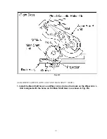
1. Install the Main Shaft Unit so that the projection on the Main Shaft Unit is aligned
with the groove on the Rack Ass'y as shown in Fig. B3.
(ALIGNMENT 3)WIPER ARM R UNIT AND MAIN SHAFT UNIT
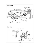
1. Position the pin of Cassette Holder Unit to the far left of the Side Plate R Ass'y slot.
2. Install the Wiper Arm R Unit so that the mark on the Wiper Arm R Unit is aligned
with the hole on the Main Shaft Unit as shown in Fig. B3.
110
Summary of Contents for PV-4601 A
Page 14: ...Fig 2 3 14 ...
Page 27: ...Fig 11 1 1 27 ...
Page 40: ...Fig D1 40 ...
Page 42: ...Fig D2 42 ...
Page 43: ...Fig D3 43 ...
Page 44: ...Fig D4 44 ...
Page 45: ...Fig D5 45 ...
Page 46: ...Fig D7 46 ...
Page 47: ...Fig D8 47 ...
Page 51: ...Fig M2 1 Fig M2 2 51 ...
Page 53: ...Fig M4 1 53 ...
Page 77: ...Fig M19 77 ...
Page 84: ...Fig J5 84 ...
Page 85: ...Fig J6 85 ...
Page 87: ...Fig J9 87 ...
Page 88: ...Fig J10 88 ...
Page 89: ...Fig J11 89 ...
Page 90: ...Fig J12 90 ...
Page 91: ...Fig J13 91 ...
Page 92: ...Fig J15 92 ...
Page 93: ...93 ...
Page 96: ...96 ...
Page 102: ...with the holes on the Pinch Lift Cam as shown in Fig A6 102 ...
Page 103: ...103 ...
Page 105: ...Fig K1 105 ...
Page 106: ...Fig K2 106 ...
Page 107: ...Fig K3 107 ...
Page 109: ...Fig B1 109 ...
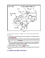
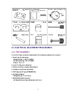
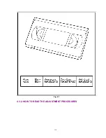
Page 114: ...Fig E1 4 3 2 HOW TO READ THE ADJUSTMENT PROCEDURES 114 ...
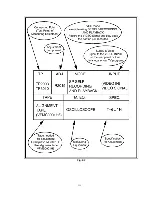
Page 115: ...Fig E2 115 ...
Page 134: ...R6004 ERJ6GEYJ333V MGF CHIP 1 10W 33K 134 ...
Page 136: ...R6085 ERJ6GEYJ223V MGF CHIP 1 10W 22K 136 ...
Page 140: ...C4601 ECEA1CKA100 ELECTROLYTIC 16V 10 140 ...
Page 147: ...R6065 ERJ6GEYJ223V MGF CHIP 1 10W 22K 147 ...
Page 167: ...9 11 Operation Block Diagrams 1 167 ...
Page 178: ......
Page 204: ......
Page 205: ......


