background image

Using the digital zoom function

(Only for still image-based signals input)

You can enlarge the center area. You can also change the location of the area to be enlarged. 

 buttons

1)  Press the <D.ZOOM +> button or < D.ZOOM -> button on the remote control.


f

The moving screen is displayed.The moving screen is displayed when executing the remote control 

operation, and the 

[DIGITAL ZOOM]

 individual adjustment screen is not displayed.


f

The 

[DIGITAL ZOOM] 

individual adjustment screen is displayed when executing the menu operation. For 

details, refer to [DISPLAY OPTION] → [OTHER FUNCTIONS] (

x

 page 73).

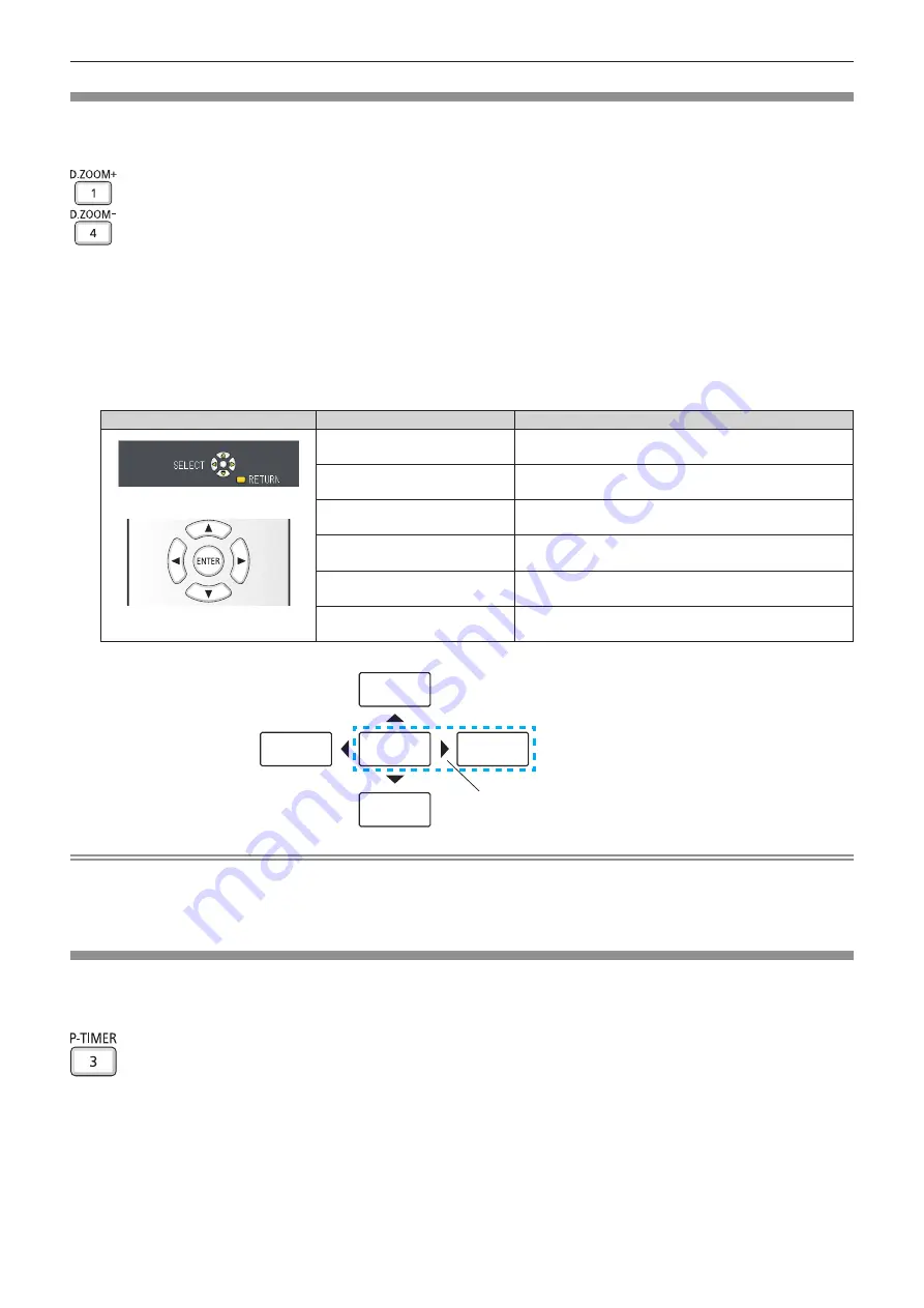
2)  Press the following buttons to move the location of the image or adjust the magnification.

Operation menu/Buttons

Operation

Adjustment

Moving screen

Remote control operation button

Press the 

a

 button.

Moves the image to the bottom.

Press the 

s

 button.

Moves the image to the top.

Press the 

q

 button.

Moves the image to the right.

Press the 

w

 button.

Moves the image to the left.

Press the <D.ZOOM +> button.

Increases magnification.

Press the <D.ZOOM -> button.

Decreases magnification.

Note


f

The magnification is not displayed in the moving screen.


f

The digital zoom function is canceled if the input signal changes during a digital zoom.


f

During a digital zoom, the freeze function is disabled.


f

The digital zoom function may not work properly for some still image-based signals.

Using the presentation timer function

You can operate the presentation timer function.
Presentations, etc. can be performed while checking the elapsed time or time remaining in the preset time.

 button

1)  Press the <P-TIMER> button on the remote control.


f

The count is started.


f

The elapsed time or the remaining time is displayed at the bottom right of the projected image.

2)  Press the <P-TIMER> button again.


f

The count is stopped.

ABC

ABC

ABC

ABC

ABC

図1

E.g. When you press the 

w


button, the display position 

moves to the left.

48 -


ENGLISH

Chapter 3  Basic Operations - Basic operations by using the remote control

Summary of Contents for PT-VX430

Page 1: ...and beyond Before operating this product please read the instructions carefully and save this manual for future use Before using your projector be sure to read Read this first x pages 4 to 12 LCD Pro...

Page 2: ...st the state of the image 44 Adjusting adjustable feet 45 Basic operations by using the remote control 46 Using the AV mute function 46 Using the mute function 46 Controlling the volume of the speaker...

Page 3: ...utions on using USB Memory 90 Displaying the Memory Viewer screen 91 Playing the pictures 91 Executing the slide 91 Termination of the Memory Viewer 91 USB display function 92 When using on a Windows...

Page 4: ...l only fit an earthing type mains socket This is a safety feature If you are un able to insert the plug into the mains socket contact an electrician Do not defeat the purpose of the earthing plug WARN...

Page 5: ...ed including interference that may cause undesired operation To assure continued compliance follow the attached installation instructions and do not make any unauthorized modifications CAUTION This eq...

Page 6: ...on safe handling procedures the measures to be taken in case of accidental breakage and safe disposal options visit ec gc ca mercure mercury Dispose of or recycle in accordance with applicable laws Po...

Page 7: ...ere electrical shock if the cut off plug is inserted into any 13 amp socket If a new plug is to be fitted please observe the wiring code as shown below If in any doubt please consult a qualified elect...

Page 8: ...all outlet Pull the power plug out from the wall outlet and wipe it with a dry cloth regularly Do not handle the power plug and power connector with wet hands Failure to observe this will result in el...

Page 9: ...disassemble dry cell batteries z z Do not heat the batteries or place them into water or fire z z Do not allow the and terminals of the batteries to come into contact with metallic objects such as nec...

Page 10: ...ctor is being used Do not block the projection by placing an object in front of the projection lens Doing so can cause fire damage to an object or malfunction of the projector z z Strong light is emit...

Page 11: ...ag or do not eat the contents If swallowed the contents of the desiccant bag accidentally it may cause bad result to your body z z If the desiccant gets into your eyes or mouth immediately rinse with...

Page 12: ...amasse a bateria O g s liberado pela bateria pode irritar a garganta danificar o lacre do inv lucro ou o vazamento provocar calor ruptura da blindagem e produzir fogo devido ao curto circuito dos ter...

Page 13: ...ly by or for Panasonic Corporation 2 the software owned by third party and licensed to Panasonic Corporation 3 the software licensed under the GNU General Public License Version 2 0 GPL V2 0 4 the sof...

Page 14: ...orrection corner correction and curved correction functions allow you to correct the image to fit the screen Useful function for presentations The Memory Viewer function enables you to project still i...

Page 15: ...Chapter 1 Preparation This chapter describes things you need to know or check before using the projector ENGLISH 15...

Page 16: ...the operating environment temperature of the projector f f Near high voltage power lines or near motors Doing so may interfere with the operation of the projector r rAsk a qualified technician or you...

Page 17: ...ojector and installation surface Make sure that there is no clearance between the screw holes for ceiling mount on the projector bottom and the installation surface by inserting spacers metallic of at...

Page 18: ...ng communication information may be leaked by a malicious third party who intentionally intercept the transmitted data g g Personal information such as your ID password and or credit card numbers g g...

Page 19: ...wing application software For details or downloading each application software visit the Panasonic website https panasonic net cns projector f f Logo Transfer Software This application software transf...

Page 20: ...cigarette smoke etc is present the replacement cycle of the LCD panel polarizing plate and other optical parts may be shorter even if used for less than one year Consult your dealer for details r rLum...

Page 21: ...signal cable 1 K1HY15YY0012 Attention f f After unpacking the projector discard the power cord cap and packaging material properly f f Do not use the supplied power cord for devices other than this p...

Page 22: ...ideo conversion cable ET ADSV Wireless Module ET WML100 1 Early Warning Software Basic license 3 year license ET SWA100 series 2 1 This product cannot be purchased in some countries For details contac...

Page 23: ...so used to enter password or characters for SECURITY 4 FREEZE button Pauses the projected image and mute the audio temporarily x page 46 5 Number 1 6 buttons Used for entering the ID number in a multi...

Page 24: ...nger f f Keep heat sensitive articles away Heated air from the air exhaust port can cause burns or external damage 1 Zoom ring Back Adjust the zoom 2 Control panel and indicators x page 25 3 Lamp cove...

Page 25: ...s of the projector 5 Ambient Luminance sensor 6 MENU button Displays or hides the main menu x page 52 When the sub menu is displayed pressing it will return to the previous screen 7 ENTER button Deter...

Page 26: ...gnals or YCB CR YPB PR signals It can also output the signals input from COMPUTER 1 IN terminal to an external device 6 HDMI 1 IN terminal HDMI 2 IN terminal These are the terminals to input HDMI sign...

Page 27: ...mber at first you need to complete the Initial setting and then after setting the ID number of the projector set the ID number on the remote control About Initial setting please refer to When the init...

Page 28: ...ss of the lens cap please attach the lens cap with the string of accessories according to the following procedures 1 Thread the thinner end of the string through the hole on the lens cap Lens cap Stri...

Page 29: ...Chapter 2 Getting Started This chapter describes things you need to do before using the projector such as the setup and connections ENGLISH 29...

Page 30: ...LING PROJECTION METHOD REAR CEILING Note f f The projector has a built in angle sensor The attitude of the projector is automatically detected by setting the PROJECTOR SETUP menu PROJECTION METHOD to...

Page 31: ...fied for this projector f f Refer to the Installation Instructions for the ceiling mount bracket when you install the bracket and the projector Attention f f To ensure projector performance and securi...

Page 32: ...8 24 0 054 5 21 8 47 0 083 5 74 9 33 0 061 6 35 250 6 34 10 30 0 067 6 52 10 59 0 104 7 19 11 67 0 076 7 62 300 7 62 12 37 0 081 7 83 12 72 0 124 8 63 14 01 0 091 For PT VX430 Unit m Projection size F...

Page 33: ...Screen height SH 0 530 SD m 0 490 SD m 0 6 SD m Screen width SW 0 848 SD m 0 872 SD m 0 8 SD m Minimum distance LW 1 0037 SD m 0 0290 1 0316 SD m 0 0290 1 1363 SD m 0 0290 Maximum distance LT 1 6273...

Page 34: ...able for connection of the device prepare a necessary system connection cable to suit the device f f Video signals containing too much jitter may cause the images on the screen to randomly wobble or w...

Page 35: ...devices Note f f For the HDMI cable use an HDMI High Speed cable that conforms to the HDMI standards If a cable that does not conform to the HDMI standards is used images may be interrupted or may no...

Page 36: ...e connected to an external device with the DVI D terminal by using an HDMI DVI conversion cable However this may not function properly for some external devices and image may not be projected f f If y...

Page 37: ...Chapter 3 Basic Operations This chapter describes basic operations to start with ENGLISH 37...

Page 38: ...connector and the AC IN terminal Consult your dealer for repairing the power cord Removing the power cord 1 Confirm that the projector is in standby mode and remove the power plug from the outlet 2 R...

Page 39: ...e power indicator ON G STANDBY R lights in orange the fan is running to cool the projector f f For about 90 seconds after the projector is switched off the luminous lamp does not light up even if the...

Page 40: ...age 44 Initial setting display language Select the language to show on the screen After completed the initial setting you can change the display language from the LANGUAGE menu 1 Press asqw to select...

Page 41: ...NTER button f f Confirm the setting value and complete the initial setting Making adjustments and selections It is recommended that images are projected continuously for at least 30 minutes before the...

Page 42: ...s going on the projector can respond with direct power off function Therefore it is also safe in case a power outage occurs or the power cord is pulled out immediately after the projector is switched...

Page 43: ...nput to VIDEO The image of the signal input to the VIDEO IN terminal is projected MEMORY VIEWER USB DISPLAY NETWORK Switches the input to MEMORY VIEWER USB DISPLAY or NETWORK If one of the inputs has...

Page 44: ...gle focus and zoom 1 Adjust the projection angle f f Place the projector on a level surface and make its front side parallel to the screen surface so that the projection screen is rectangular f f If t...

Page 45: ...st the adjustable feet by turning them Turn the adjustable feet counterclockwise as shown in the figure to extend them Also turning them clockwise will return to the original status Feet lock latches...

Page 46: ...off button 1 Press the MUTE button on the remote control f f The audio turns off 2 Press the MUTE button again f f The audio turns on Controlling the volume of the speaker The volume of the built in s...

Page 47: ...ment the automatic adjustment will be canceled f f If the automatic setup function is used while moving images are being input the adjustment may not be performed properly even for a signal that can u...

Page 48: ...s the image to the right Press the w button Moves the image to the left Press the D ZOOM button Increases magnification Press the D ZOOM button Decreases magnification Note f f The magnification is no...

Page 49: ...The Daylight View function improves the vividness of the image even if it is projected under a bright light button 1 Press the DAYLIGHT VIEW button on the remote control f f It will switch each time y...

Page 50: ...s to its original value before the ID SET button was pressed f f The ID number set on the remote control will be stored unless it is set again However it will be erased if the remote control is left w...

Page 51: ...Chapter 4 Settings This chapter describes the settings and adjustments you can make using the on screen menu ENGLISH 51...

Page 52: ...CURITY NETWORK USB ENTER SELECT RETURN FUNCTION ASSIGNED FUNCTION DISABLE ON SCREEN DISPLAY HDMI SIGNAL LEVEL CLOSED CAPTION SETTING SCREEN SETTING STARTUP LOGO DEFAULT LOGO AUTO SETUP SETTING AUTO ON...

Page 53: ...er to Main menu x page 53 and Sub menu x page 54 Resetting adjustment values to the factory default If the DEFAULT button on the remote control is pressed the values adjusted in the menu items are res...

Page 54: ...N HDMI 2 IN terminal is selected Note f f The factory default settings may vary depending on the picture mode POSITION Sub menu item Factory default Page REALTIME KEYSTONE ON 61 SCREEN ADJUSTMENT 61 S...

Page 55: ...ASSWORD CHANGE 82 TEXT DISPLAY OFF 82 TEXT CHANGE 83 MENU LOCK OFF 83 MENU LOCK PASSWORD 83 CONTROL DEVICE SETUP 83 NETWORK USB Sub menu item Factory default Page WIRED LAN 85 NAME CHANGE 85 NETWORK C...

Page 56: ...or the movie based signals 2 Only for the still image signals CONTRAST You can adjust the contrast of the colors 1 Press as to select CONTRAST 2 Press qw or the ENTER button f f The CONTRAST individua...

Page 57: ...creen is displayed 3 Press qw to adjust the level Operation Adjustment Adjustment range Press the w button Contours become sharper 0 15 Press the q button Contours become softer Note f f SHARPNESS wil...

Page 58: ...dow areas 32 32 Press the q button Deemphasizes red in shadow areas BRIGHTNESS G Press the w button Emphasizes green in shadow areas 32 32 Press the q button Deemphasizes green in shadow areas BRIGHTN...

Page 59: ...en this is set for an input signal with less noise the image may look different from what it originally was In such a case set it to OFF TV SYSTEM Only for VIDEO signal input The projector will automa...

Page 60: ...ignal input When COMPUTER 1 COMPUTER 2 input is selected f f For 525i 480i 625i 576i 525p 480p and 625p 576p input Select AUTO RGB or YCB CR f f For other movie based signal input Select AUTO RGB or Y...

Page 61: ...he ENTER button f f The SCREEN ADJUSTMENT screen is displayed 3 Press as to select one item to adjust KEYSTONE Adjusts when the projected image is distorted as trapezoid CORNER CORRECTION Adjusts when...

Page 62: ...tting CORNER CORRECTION 1 Press as to select SCREEN ADJUSTMENT 2 Press the ENTER button f f The SCREEN ADJUSTMENT screen is displayed 3 Press as to select CORNER CORRECTION 4 Press the ENTER button f...

Page 63: ...izontal line will be bulge Press the w button The top and the bottom of horizontal line will be dent V Press the a button The left and the right of vertical line will be dent Press the s button The le...

Page 64: ...tern may cause cyclic patterns noise Adjust so that the amount of interference is at a minimum 1 Press as to select DOT CLOCK 2 Press qw or the ENTER button f f The DOT CLOCK individual adjustment scr...

Page 65: ...displayed with the top and bottom parts cut off V FIT Displays the height of the panel pixels vertically without changing the aspect ratio when wide screen signals are input When signals have the aspe...

Page 66: ...f f The FRAME LOCK individual adjustment screen is displayed 3 Press qw to switch the FRAME LOCK f f The items will switch each time you press the button ON The frame is locked Synchronizes the displ...

Page 67: ...GU S PT VW360 LANGUAGE DISPLAY OPTION PROJECTOR SETUP SECURITY NETWORK USB ENTER SELECT RETURN ASSIGNED FUNCTION DISABLE 1 2 f f Various menus settings adjustment screens control button names etc are...

Page 68: ...position of the menu screen OSD 1 Press as to select ON SCREEN DISPLAY 2 Press the ENTER button f f The ON SCREEN DISPLAY screen is displayed 3 Press as to select OSD POSITION 4 Press qw to switch the...

Page 69: ...nnected external device Refer to the operation instruction of the external device regarding the output of the external device f f The displayed signal level is assumed when the input is 30 bits CLOSED...

Page 70: ...ch time you press the button Model No SCREEN FORMAT The available items to set when SCREEN POSITION is selected PT VW360 16 10 Cannot be set 16 9 Three items of CENTER HIGH and LOW can be selected for...

Page 71: ...detection function OFF Disables the input detection function BACK COLOR Set the display of the projected screen when there is no signal input 1 Press as to select BACK COLOR 2 Press qw to switch the...

Page 72: ...e set by TIMER Setting the countdown timer 1 Press as to select TIMER 2 Press qw to set the timer f f The time can be set in 1 minute increments from 1 to 180 minutes f f The factory default value is...

Page 73: ...to release this function AV MUTE Turn off audio and image when the projector is not used for a certain period of time You can also deactivate the function by pressing the RETURN button or the AV MUTE...

Page 74: ...ou attach a lamp unit used in a projector of a model different from the projector PT VW360 PT VX430 to the projector or when the lamp unit used in the projector to a projector of a different model the...

Page 75: ...rts up in the status that before removing the power plug from the outlet or turning off the circuit breaker STANDBY Starts up in the standby mode ON Starts the projection immediately PROJECTION METHOD...

Page 76: ...g environment of the projector or the purpose 1 Press as to select LAMP POWER 2 Press qw to switch the item f f The items will switch each time you press the button NORMAL Select when high luminance i...

Page 77: ...ion from 5 minutes to 120 minutes in increments of 5 minutes 1 Press as to select TIMER 2 Press qw to set the timer f f The time will switch each time you press the button Setting STANDBY MODE in Step...

Page 78: ...5000 series DZ570 series DW530 series DX500 series RZ970 series RW930 series RX110 series RZ770 series RZ660 series RW730 series RW620 series RZ670 series RW630 series RZ575 series RZ570 series L730 S...

Page 79: ...item OFF Outputs the audio ON Turns off the volume temporarily Setting the audio output during standby 1 Press as to select AUDIO SETTING 2 Press the ENTER button f f The AUDIO SETTING screen is displ...

Page 80: ...O IN AUDIO IN 1 AUDIO IN 2 or AUDIO IN 3 MEMORY VIEWER LIGHT Select one item among AUDIO IN 1 AUDIO IN 2 or AUDIO IN 3 USB DISPLAY Select one item among USB DISPLAY AUDIO IN AUDIO IN 1 AUDIO IN 2 or A...

Page 81: ...n f f The FILTER COUNTER screen is displayed 3 Press as to select FILTER COUNTER RESET 4 Press the ENTER button 5 When the confirmation screen is displayed press qw to select OK and then press the ENT...

Page 82: ...button OFF Disables the security password entry ON Enables the security password entry Note f f The PASSWORD setting is set to OFF by the factory default f f The security password input when turning o...

Page 83: ...ng after executing the PROJECTOR SETUP menu INITIALIZE ALL is set to OFF Set it to ON if necessary f f When MENU LOCK is set to ON the MENU LOCK PASSWORD screen is displayed after pressing the MENU bu...

Page 84: ...irmation screen will be displayed when you change ENABLE to DISABLE then proceed to Step 5 5 Press qw to select OK and then press the ENTER button Note f f When a button operation is performed on the...

Page 85: ...s set to OFF SUBNET MASK Enter the subnet mask when DHCP is set to OFF DEFAULT GATEWAY Enter the default gateway address when DHCP is set to OFF DNS1 Enter the preferred DNS server address when DHCP i...

Page 86: ...em f f The items will switch each time you press the button OFF This function is disabled ON This function is enabled Crestron Connected TM Set to ON to control with Crestron Connected of Crestron Ele...

Page 87: ...the ENTER button f f The setting will be effective ROTATE Sets the rotational direction of the images 1 Press as to select ROTATE 2 Press qw to switch the item f f The items will switch each time you...

Page 88: ...s of wired LAN WIRELESS LAN SSID 1 Displays the character string of SSID IP ADDRESS 1 Displays the IP address Presenter Light LOGIN PASSWORD Displays the login password of Presenter Light 1 The SSID I...

Page 89: ...Chapter 5 Operation of Function This chapter describes the operation methods of some functions ENGLISH 89...

Page 90: ...al It may cause data loss or data corruption f f Do not remove the USB memory from the computer or the projector while the USB memory is reading out the data It may cause data loss or data corruption...

Page 91: ...pect ratio f f When the recorded number of pixels is larger than the maximum number of display dot 1 it will be displayed reduced maintaining the aspect ratio f f When the recorded number of pixels is...

Page 92: ...iver which is built in the projector and executing the installation according to the instructions of the screen The displaying of the auto installation screen is depending on the settings of computer...

Page 93: ...f f The item which is displayed in gray is unavailable Active audio Disable audio The audio output is disabled Play video Pause video Switch between playing and pausing the image Start Stop Set wheth...

Page 94: ...tails please refer to About Presenter Light x page 97 The applicaton software and its operating instructions can be downloaded from our website https panasonic net cns projector For details of the ima...

Page 95: ...ting according to your system administrator f f If the projector settings are the default settings the computer can be used with the following network settings IP ADDRESS 192 168 10 101 SUBNET MASK 25...

Page 96: ...of the wireless module is not lighting blinking please insert the wireless module to the USB A VIEWER WIRELESS terminal again f f After turning on the projector please connect network to the projecto...

Page 97: ...uch a case please select mute in the audio setting of the application software Download the Presenter Light to your computer 1 Start up the web browser on the computer 2 Enter the IP address set on th...

Page 98: ...is used as the executable file format It cannot be installed in the computer f f Execute this file when using the software Please save this software or make a shortcut for convenient use Note f f For...

Page 99: ...connected via the network from a computer This projector supports Crestron Connected f f For details of Crestron Connected please refer to the website of Crestron Electronics Inc Only in English URL...

Page 100: ...es for PT VW360 Screen content may differ from that for the projector model you are using In addition the screen size and the display may differ from this manual depending on the OS web browser or the...

Page 101: ...PT VW360 000000000 1 PROJECTOR TYPE Displays the type of the projector 2 MAIN VERSION Displays the firmware version of the projector 3 POWER Displays the status of the power 4 PICTURE MODE Displays t...

Page 102: ...be blocked OPTICS MODULE TEMPERATURE The temperature around the optics module inside the projector is high The projector may be used in an operating environment where the temperature is high such as n...

Page 103: ...input to be projected 2 VOLUME Adjusts the volume level 3 PICTURE MODE Switches the picture mode 4 AV MUTE Switches between AV mute on off 5 POWER Turns on off the power 6 CLOSED CAPTION Switches the...

Page 104: ...way address when not using a DHCP server 6 DNS1 Enters the DNS1 server address Permissible characters for the entry of DNS1 server address preferred Numbers 0 9 period Example 192 168 0 253 7 DNS2 Ent...

Page 105: ...cted to the LAN may cause the connection to cut out f f The setting values of the Network config page will return to the factory default when the INITIALIZE of the NETWORK USB menu is executed x page...

Page 106: ...il can be sent to preset E mail addresses up to two addresses Click Detailed set up E mail set up 1 2 3 4 5 6 1 ENABLE Select Enable to use the E mail function 2 SMTP SERVER NAME Enter the IP address...

Page 107: ...uthentication set up page Set the authentication items when POP authentication or SMTP authentication is necessary to send an E mail Click Detailed set up Authentication set up 1 2 3 4 5 6 7 8 1 Auth...

Page 108: ...IR TEMPERATURE OK OPTICS MODULE TEMPERATURE OK LAMP REMAIN TIME OK LAMP STATUS OK APERTURE CONTRAST SHUTTER OK INTAKE AIR TEMP SENSOR OK OPTICS MODULE SENSOR OK EXHAUST AIR TEMP SENSOR OK AIR FILTER O...

Page 109: ...0 00 02 00 00 00 00 Intake air temperature 28 degC 82 degF Exhaust air temperature 34 degC 93 degF Optics module temperature 38 degC 100 degF PROJECTOR RUNTIME 16 H LAMP ECO 0 H LAMP NORMAL 7 H LAMP R...

Page 110: ...nt Administrator Displays the account to change 2 Current User name Enter the user name before the change Password Enter the current password 3 New User name Enter the desired new user name Up to 16 c...

Page 111: ...s the change of password Note f f To change the account of the administrator you must enter the User name and the Password in Current Crestron Connected TM page The projector can be monitored controll...

Page 112: ...e previous page Tools page Click Tools on the control page 1 2 3 4 5 1 Control System Sets the information required for communicating with the controller to be connected with the projector 2 User Pass...

Page 113: ...isplays the status of the power 5 Source Displays the selected input 6 Lamp Mode Displays the setting status of LAMP POWER 7 Error Status Displays the error status 8 Exit Returns to the control page H...

Page 114: ...Chapter 6 Maintenance This chapter describes methods of inspection when there are problems maintenance and replacement of the units 114 ENGLISH...

Page 115: ...rd and consult your dealer Note f f If the lamp indicator LAMP is still lighting or blinking after taking the preceding measures ask your dealer for repair Warning indicator WARNING Indicator status L...

Page 116: ...ousehold cleaners Using them may cause deterioration of the lens Attention f f The lens may be damaged if you hit with a hard object or wipe with excessive force Please handle with care Replacing the...

Page 117: ...t Attention f f Turn off the power before you replace the air filter unit f f When attaching the air filter unit make sure that the projector is stable and work in an environment that is safe even in...

Page 118: ...e model numbers of accessories and optional accessories are subject to change without prior notice When to replace the lamp unit The lamp unit is a consumable component Since its brightness gradually...

Page 119: ...ng screws 3 until they turn freely 4 Hold the used lamp unit by its handles and pull it gently from the projector 5 Insert the new lamp unit in correct direction Tighten the three lamp unit fixing scr...

Page 120: ...46 79 46 73 35 46 79 79 The remote control does not operate f f The batteries may be weak f f The batteries may not have been inserted correctly f f The remote control signal receptor on the projector...

Page 121: ...Chapter 7 Appendix This chapter describes specifications and after sales service for the projector ENGLISH 121...

Page 122: ...rors and returns 0 2 4th byte Indicates cover open er rors and returns 0 or 2 5th byte Indicates filter errors and returns 0 2 6th byte Indicates other errors and returns 0 or 2 LAMP Luminous lamp st...

Page 123: ...rotect mode 3 Generate a 32 byte hash value from the following data using MD5 algorithm f f xxxxxx yyyyy zzzzzzzz xxxxxx Administrator rights user name for web control Default user name is dispadmin y...

Page 124: ...ength 9 bytes 1 byte 1 byte 1 byte f fMode 0 Non protect mode Command data format It is the data format used for sending and receiving commands r r Transmitted data Header Data section Termination sym...

Page 125: ...view Pin No Signal name Contents NC TXD Transmitted data RXD Received data NC GND Earth NC CTS Connected internally RTS NC Communication conditions The communication conditions differ depending on th...

Page 126: ...ceiving the response from the projector before sending the next command When transmitting a command which does not need a parameter a colon is not necessary Note f f If a command cannot be executed th...

Page 127: ...own Q L Luminous lamp cumulative runtime query 1 Returned with 0 to 99999 OSH AV mute control 0 AV mute function off QSH AV mute status query 1 AV mute function on Q S Luminous lamp condition query 0...

Page 128: ...080i 27 0 48 0 74 3 R Y H 1125 1080 25p 1 920 x 1 080 28 1 25 0 74 3 R Y H 1125 1080 30p 1 920 x 1 080 33 8 30 0 74 3 R Y H 1125 1080 60p 1 920 x 1 080 67 5 60 0 148 5 R Y H l 1125 1080 50p 1 920 x 1...

Page 129: ...080 55 6 49 9 141 5 R H 1 920 x 1 080 4 66 6 59 9 138 5 R H WUXGA 1 920 x 1 200 61 8 49 9 158 3 R H 1 920 x 1 200 4 74 0 60 0 154 0 R H 1 Where marked l signals indicates in Plug and Play is compatibl...

Page 130: ...anual zoom 1 6x Manual focus F 1 6 to 1 9 f 15 31 mm to 24 64 mm Luminous lamp 240 W UHM lamp Light output 1 PT VW360 4 000 lm PT VX430 4 500 lm When PICTURE MODE is set to DYNAMIC LAMP POWER is set t...

Page 131: ...tic positive negative polarity compatible The SYNC HD and VD terminals do not support 3 value SYNC YPB PR signal Y 1 0 V p p including synchronization signal PB PR 0 7 V p p 75 Y C signal Y 1 0 V p p...

Page 132: ...o signal input Horizontal 15 73 kHz Vertical 59 94 Hz Horizontal 15 63 kHz Vertical 50 Hz For Y C signal input Horizontal 15 73 kHz Vertical 59 94 Hz Horizontal 15 63 kHz Vertical 50 Hz For RGB signal...

Page 133: ...ensions Unit mm inch 113 4 7 16 255 10 1 32 352 13 27 32 24 15 16 98 3 27 32 90 3 17 32 326 12 27 32 198 7 25 32 59 2 5 16 Actual dimension may differ by product ENGLISH 133 Chapter 7 Appendix Dimensi...

Page 134: ...f Unused products must be removed promptly by a qualified technician f f Use a torque screwdriver or Allen torque wrench to tighten bolts to their specified tightening torques Do not use electric scre...

Page 135: ...LECT button Projector body 25 43 Installation mode 30 IRIS 57 K KEYSTONE 61 L Lamp indicator 25 115 LAMP POWER 76 LANGUAGE 67 LAN terminal 26 List of compatible signals 128 M Main menu 53 Maintenance...

Page 136: ...877 803 8492 TEL 905 624 5010 Panasonic Canada Inc Disposal of Old Equipment and Batteries Only for European Union and countries with recycling systems These symbols on the products packaging and or a...

Reviews: