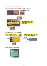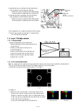
6. Remove 5 screws (5 x otype silver tap screws) then remove the optical block.
* Disconnect the flex cable on D-PCB from the laser unit, then proceed the removal step of optical block.
* Lift the optical block a little, then disconnect 2 cables on D-PCB from LED unit.
* Disconnect 1 cable on PD-PCB.
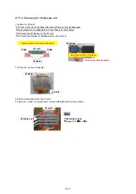
7. Remove 3 screws (o type silver screws with washers) then remove the lens unit from the DMD block.
* Please watch carefully not to loose the SIM spacers between lens unit and DMD block.
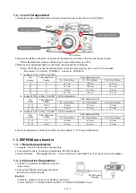
8. Remove 3 screws (3mm hex screws) then separate the DMD block from the lighting block.
DMD block
Lighting block
XVE4A10FT
(3mm
hex
screw)
100
±
20
N
・
cm
XYN3+F20FJ
Lens unit
70
±
10
N
・
cm
105
±
15
N
・
cm
Optical block
* Peel off the aluminum tape at the position of screw hole.
XTB4+12GFJ
[ CAUTION ]
Unplug the Flex cable before
remove the optical block.
<Optical block>
DIS-8
Summary of Contents for PT-RZ470 Series
Page 6: ...6 2 Specifications...
Page 7: ...7...
Page 9: ...INF 2 1 The name of each part 1 1 Projector body 1 2 Control panel...
Page 10: ...INF 3 1 3 Connecting terminals 1 4 Remote control...
Page 11: ...INF 4 2 OSD Menu Navigation...
Page 12: ...INF 5...
Page 13: ...INF 6...
Page 26: ...INF 19 5 Select Log SYSTEM and click Get button 6 Log is displayed...
Page 84: ......

