


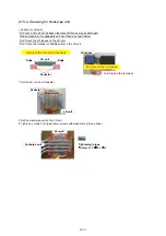


2. 2. Removal of Top cover, Front cover and Side cover R
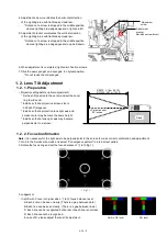
1. Remove 14 screws (TORX type : silver tap screw) then open the top cover.
* Please use Hexlobe (TORX type) driver.
2. Remove 2 screws (o type : black tap screw) then remove the front cover.
3. Remove 5 screws (o type : black tap screw) then remove the Side cover R.
* Remove 3 screws (o type : black tap screw with washers) then remove S-PCB from Side cover R.
Front cover
XTBT969FJK
Side cover R
THTA072N
THTA072N
THTA072N
THTA072N
S -PCB
Side cover R
XTBT969FJK
XYC3+FG10FJK
DIS-5
Summary of Contents for PT-RZ470 Series
Page 6: ...6 2 Specifications...
Page 7: ...7...
Page 9: ...INF 2 1 The name of each part 1 1 Projector body 1 2 Control panel...
Page 10: ...INF 3 1 3 Connecting terminals 1 4 Remote control...
Page 11: ...INF 4 2 OSD Menu Navigation...
Page 12: ...INF 5...
Page 13: ...INF 6...
Page 26: ...INF 19 5 Select Log SYSTEM and click Get button 6 Log is displayed...
Page 84: ......