background image

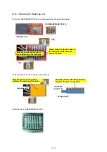
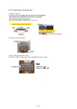
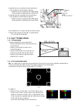
< Notice >

* Please pull horizontally the flat type connection terminal of

   the LED unit, while holding the part of an arrow.

  2. 9. Removal of Phosphor wheel

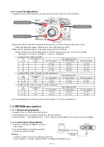
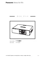
1. Remove top cover in accordance with the procedure till 2.2 1

2. Remove 3 screws (2 x ordinal  type black tap screws and 1 x o type silver screw with washers) 

    then remove duct top R and B duct plate.

3. Remove 7 screws (6 x o type silver screws with washers and 1 one way screw) 

    then remove the top cover of lighting block.

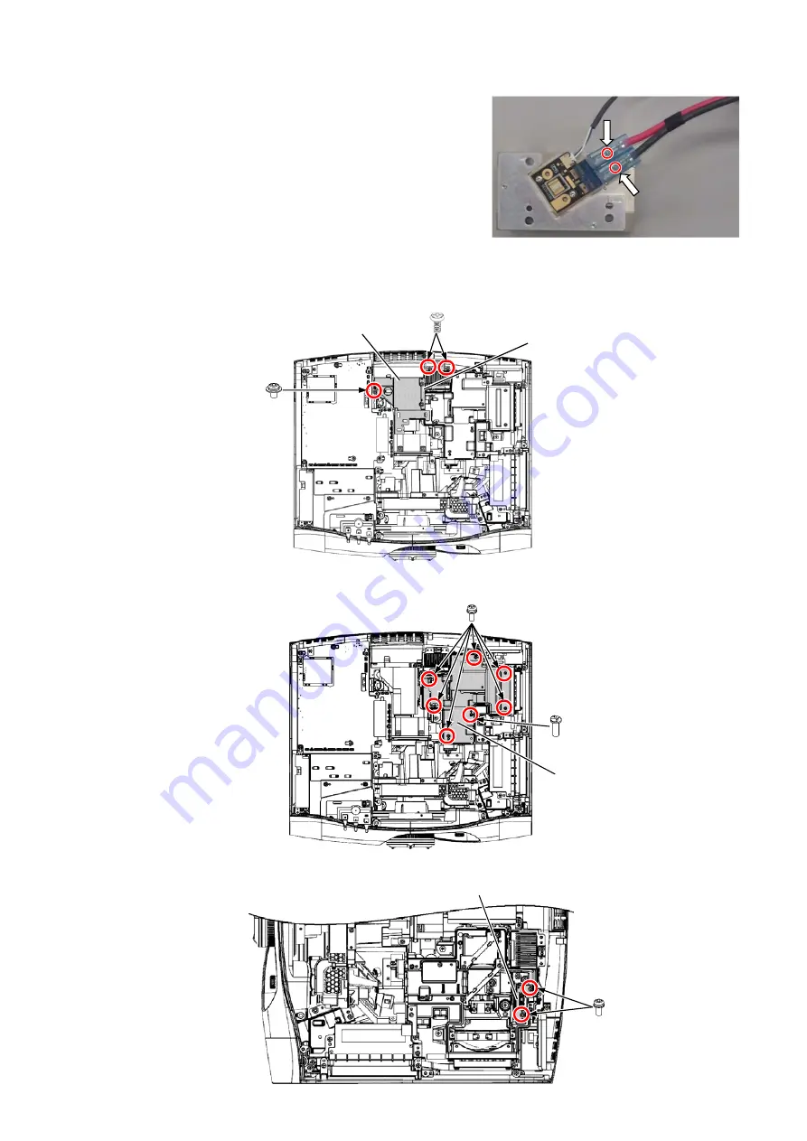
4. Remove 2 screws (o type screws with washers) then remove the phosphor wheel.

XYN3+F6FJ

XTBT969FJK

Duct top R

B duct plate

XYN3+J8FJ

Phosphor wheel 

XYN3+J8FJ

THEJ054W

Top cover of lighting block

*Please use the One-sided screw 

removal tool.

* When tightening the screws, 

lease use a flat-blade 

screwdriver.

DIS-13

Summary of Contents for PT-RZ470 Series

Page 1: ...1 20 000 1 Added EDGE BLENDING function Added BRIGHTNESS CONTROL function Equipped with 3D SYNC terminal and added 3D projection function VESA standard IR system DLP Link system Available in portrait...

Page 2: ...about lead free solder Sn Ag Cu tin silver and copper will tend to splash when heated too high approx 600 C or higher Use lead free solder for the P C Board specified on it as PbF which uses lead fre...

Page 3: ...and if not installed and used in accordance with the instructions may cause harmful interference to radio communications However there is no guarantee that interference will not occur in a particular...

Page 4: ...Instructions 1 Adjustment Procedure 2 Software update procedure 1 Block Diagram 2 Interconnection Block Diagram 3 Schematic Diagram 4 Circuit Boards Diagram 1 Exploded Views 2 Replacement Parts List T...

Page 5: ...electric shock For continued safety no modification of any circuit must be attempted Unplug the power cord from the power outlet before disassembling this projector Use correctly the supplied power co...

Page 6: ...6 2 Specifications...

Page 7: ...7...

Page 8: ...Mode 4 External control INF 10 4 1 Control through SERIAL termanal 4 2 Control through LAN terminal 5 Notification for service operation INF 14 5 1 Before service operation 5 2 Service 5 3 Initializa...

Page 9: ...INF 2 1 The name of each part 1 1 Projector body 1 2 Control panel...

Page 10: ...INF 3 1 3 Connecting terminals 1 4 Remote control...

Page 11: ...INF 4 2 OSD Menu Navigation...

Page 12: ...INF 5...

Page 13: ...INF 6...

Page 14: ...Main Menu will be displayed 3 3 Function of Service Mode 3 3 1 EXT OPTION EXTRA OPTION is added to the bottom of the main menu 1 EXTEND PROJECTOR ID ON PROJECTOR ID can be set to ALL and 1 64 OFF PRO...

Page 15: ...LOG SENSOR CALIBRATION Calibrate the clogging sensor circuit Execute this after EEPROM IC1405 A P C Board or Airflow sensor M3 P C Board is replaced Refer to the SECTION3 ADJUSTMENT PROCEDURE about me...

Page 16: ...r company products OTHER Other company products MODE_SH Other company products 2 The following items are added on STATUS sub menu page 1 3 OPTICS MODULE TEMP EMULATE VERSION 3 The following items are...

Page 17: ...S 232C so that the projector can be connected to and controlled from a computer 9 9 Projector SERIAL IN terminal Computer DTE specifications NC CTS Connected each other inside RTS NC 2 3 4 5 6 Signal...

Page 18: ...ically please refer to Control Commands List 8 Response of basic control commands In accepted period It depends on each command Out of accepted period or no command Parameter or REMOTE 2 terminal is a...

Page 19: ...1 byte 1 byte ASCII character Non defined length Hash value 32 bytes Refer to item3 in 4 2 2 1 0 Control command 0x0d Header CR Data Terminal symbol 0 CR 0x30 0x30 0x30 ASCII character 0 1 byte 9 byt...

Page 20: ...2 Receive the response from projector Responding data Mode 0 Non protect mode 4 2 3 2 Command transmission Send the command with the style below Transmission data Receiving data Error response ERR1 C...

Page 21: ...ote that such phenomena does not indicate malfunction 2 This is not a malfunction Directing a high power laser beam onto the lens surface can damage the DMD chips 5 1 3 Lithium battery 1 The lithium b...

Page 22: ...se cover Lighting top case INF 15 When replacing the print board the internal electrical parts can be broken by the static electricity of clothes or human body Be careful of static electricity and wea...

Page 23: ...is changed into a parallel light by P Collimate lens1 3 and enters into a rod integrator The light of each LED changes emission light into parallel light by each collimate lens lets each dichroic mirr...

Page 24: ...faulty DMD drive circuit is faulty or Signal processing unit PCB is faulty or Connector connection is faulty Top cover is not installed Abnormalities in fan connection Fan failure Connection problem w...

Page 25: ...32C INPUT SELECT of PROJECTOR SETUP menu 6 3 3 Acquisition of log data 1 Switch the projector to Normal Standby mode POWER indicator is Lighting in red 2 Start up service software DataLogBackup exe wi...

Page 26: ...INF 19 5 Select Log SYSTEM and click Get button 6 Log is displayed...

Page 27: ...000 Intake temperature sensor trouble Breaking of intake temperature sensor or disconnect of connector A22 35 00000008 00000000 Unused 36 00000010 00000000 Unused 37 00000020 00000000 Battery low volt...

Page 28: ...00000 Unused 94 00000000 40000000 Unused 95 00000000 80000000 Unused 96 00000001 00000000 Unused 97 00000002 00000000 Network microprocessor communication error Network microprocessor no response 98 0...

Page 29: ...ors or install top cover properly Follow the section A PCB operation checks The projector does not change from standby mode to an operating mode The power indicator does not change from red to green C...

Page 30: ...on is changed to ON check the rotation noise of phosphor wheel Check the phosphor wheel Function and Connection P Check short circuits of P2 connector pin 1 3 DC390V 20V Check short circuits of P2 con...

Page 31: ...f input signal A Check the IC1300 and its associated circuits Either projection image of DVI I digital or HDMI can be checked Either projection image of COMPUTER or DVI I Analog can be checked Check t...

Page 32: ...the sync signal input waveform of IC1010 Check the output waveform Q1025 HD Q1026 VD A Check the following components and its associated circuits C1011 Q1025 C1012 Q1026 HD VD Check the IC1400 and its...

Page 33: ...circuits DVI I Digital input checks Either projection image of COMPUTER or VIDEO or DVI I Analog can be checked Projection image of HDMI can be checked Check the IC1012 and its associated circuits A C...

Page 34: ...een 12 dB or lower or Yellow 11 to 8 dB A Check the following components and its associated circuits JK2001 IC2001 X2001 IC2002 IC2003 A Check the output waveform of IC1300 FPGA R1373 HS R1372 VS R136...

Page 35: ...erly Check the clock frequency of X1402 20MH Check the X1402 and its associated circuits Check the IC1405 IC1406 and IC1407 Replace IC1405 IC1406 or IC1407 Check the A PCB and B PCB Network does not w...

Page 36: ...ace G PCB Control panel does not work Cable check of A9 S1 connector Replace cable Replace R PCB SERIAL IN does not work Confirm the connection of RS 232C cable SERIAL IN Connect it properly or replac...

Page 37: ...its associated circuits Audio function does not work G Analog Check the cable connected to AUDIO Connect it properly or replace cable G Adjustment of volume will change in waveform IC4002 13 pin R 2...

Page 38: ...l of Top cover Front cover and Side cover R 2 3 Removal of A P C Board Block 2 4 Removal of Optical Block 2 5 Removal of D P C Board 2 6 Removal of B P C Board 2 7 Removal of P P C Board 2 8 Removal o...

Page 39: ...ing system Central processing unit Interface of control terminals Color sensor Formatter for DMD Control switch panel Indicator Front IR receiver Phosphor wheel rotation sensor Board name A G PD FM Po...

Page 40: ...nel R side panel Terminal cover B PCB block V PCB block P PCB A PCB Optical block D PCB LD G fan LED B fan LED R fan DMD fan Exhaust fan Drive fan DMD block Lighting block Lens unit LED R unit LED B u...

Page 41: ...ug from the wall outlet Please wear protective gloves not to be hurt with a metal part or a shield board When assembling reverse the disassembly procedures When tore off sticky tapes and sponges pleas...

Page 42: ...emove 2 screws ordinal type black tap screw then remove the front cover 3 Remove 5 screws ordinal type black tap screw then remove the Side cover R Remove 3 screws ordinal type black tap screw with wa...

Page 43: ...the body 3 Remove 4 screws ordinal type silver screw then remove the terminal cover from A PCB block 4 Remove 9 screws 3 x ordinal silver screws with washers 1 ordinal silver screw 1 ordinal black ta...

Page 44: ...remove the duct top G2 4 Remove 3 screws 2 x black tap screws and 1 silver screw with washers then remove duct top R and B duct plate 5 Remove one screw one way screw then remove the lighting case cov...

Page 45: ...al type silver screws with washers then remove the lens unit from the DMD block Please watch carefully not to loose the SIM spacers between lens unit and DMD block 8 Remove 3 screws 3mm hex screws the...

Page 46: ...remove duct top G1 2 Remove 2 screws ordinal type silver screw with washers then remove LD G fan 3 Remove 1 screw ordinal type silver screw with washers then remove Drive fan 4 Remove 4 screws ordina...

Page 47: ...type silver screws with washers then remove LED B fan 7 Remove 2 screws ordinal type black tap screws then remove the duct bottom B 8 Remove 4 screws ordinal type silver screws with washers then remov...

Page 48: ...s then remove the B PCB block 3 Remove 4 screws ordinal type silver screws with washers then remove B PCB 2 7 Removal of P P C Board 1 Remove B PCB in accordance with the procedure till 2 6 2 2 Remove...

Page 49: ...t assembling and grease painting procedure 4 Remove 3 screws on each color ordinal type silver screws with washers then remove LED B unit and LED R unit LED B unit LD unit LED R unit XYN3 F16FJ Heat p...

Page 50: ...ew with washers then remove duct top R and B duct plate 3 Remove 7 screws 6 x ordinal type silver screws with washers and 1 one way screw then remove the top cover of lighting block 4 Remove 2 screws...

Page 51: ...5 When assembling the sponge of a lighting top case sticks a new sponge on the original position TMKH589 8 TMKH512 1 Reference Wiring diagram DIS 14...

Page 52: ...LD unit and Heat pipe Please purchase this grease locally Information of grease Manufacturer Shin Etsu Chemical Co Ltd Item Thermal Interface compounds High reliability Model G 776 Packing 100g or 1kg...

Page 53: ...GREASE MASK PLATE Heat pipe unit Please make sure that the boss of the Heat pipe is fitted into the hole of the plate Clip Clip Please make sure that the plate is flat and attached to the Heat pipe H...

Page 54: ...unit Don t touch the terminal of flexible cable on the LD unit 1 Set the LD unit on a Pedestal 2 Set the Heat pipe unit on the LD unit 3 Tighten 4 screws A Original silver screws with washers by torq...

Page 55: ...nsor calibration 1 6 Drive current White balance Color luminance adjustment 1 7 Color luminance adjustment 2 Software Update procedure ADJ 13 2 1 Update by LAN Terminal connection Main Sub Network Mic...

Page 56: ...the fixing screws 2 pcs in hex driver 2 5mm 1 1 Lighting area adjustment DMD block Lens unit A P C Board Save data to a PC before A PCB exchange and write it into a new A PCB Adjustment Items 1 4 Mode...

Page 57: ...2 29m 90 diagonal Installs so that a projection lens light axis and screen center may become the same height Installs so that a lens optic axis may become perpendicular to a screen 1 2 2 Focus Confirm...

Page 58: ...unication cable D sub 9pin male female RS 232C straight 3 Service Software DataLogBackup tool Service software is downloaded from the projector service homepage 1 3 2 Connection Preparations Caution C...

Page 59: ...mode POWER indicator is Lighting in red 2 Start up service software DataLogBackup exe with a computer 3 Select Option Setting and set Serial Port of the computer Baud Rate and Parity 4 Select a model...

Page 60: ...Start up service software DataLogBackup exe with a computer 3 Select Option Setting and set Serial Port of the computer Baud Rate and Parity 4 Select a model number and ID 6 Select the file and click...

Page 61: ...place and push the ENTER button 3 Select OK and push ENTER button Then calibration starts While calibrating the image becomes all white Do not turn off the projector while calibration process is on g...

Page 62: ...e download from service web page 1 6 2 Preparation 1 Set the projector lens at center position with wide end zoom 2 Set the throw distance at 1 25 1 30m approx 40inch 3 Connect serial cable between pr...

Page 63: ...ctor In this case select Option Setting PJ Projector and computer is connected Port No Baud Rate Parity please set correctly 4 1 Select to Option Setting CL 200 2 CL 200 and computer is connected Port...

Page 64: ...the progress bar reaches the right end Current adjustment is complete Finished message is displayed 4 Click the OK button or after 3 seconds progress will start White Balance adjustment When the prog...

Page 65: ...e completed click OK button or click X then return to the service tool screen Note When displayed as NG please redo adjustment again 8 Please close the service tool by clicking the Exit button 9 Reboo...

Page 66: ...hen the progress bar reaches the right end aging is complete Finished message is displayed 3 Click the OK button or after 3 seconds progress will start Color Luminance adjustment When the progress bar...

Page 67: ...in advance prevent be in the standby shut down state DIGITAL LINK MODE of the NETWORK menu on projector set to AUTO or ETHERNET 2 1 3 Update procedure 1 Switch the projector to Normal Standby mode PO...

Page 68: ...eforehand and click Open button Confirm that it is OK and click Update 8 Click OK button and start update 7 When load of the microcomputer software is completed a checkmark and path and a version are...

Page 69: ...homepage to the PC 2 2 2 Connection Preparations Set up a PC in advance prevent be in the standby shut down state 2 2 3 Update procedure 1 Switch the projector to Normal Standby mode POWER indicator i...

Page 70: ...esult of the connection confirmation is displayed Check OK Click OK button and advance next Check NG Come back to item 3 and please confirm whether setting is right 5 Select Microprocessor to update a...

Page 71: ...se confirm whether the version of the Microprocessor Software is updated definitely with sub menu STATUS of the main menu PROJECTOR SETUP 7 When load of the microcomputer software is completed a check...

Page 72: ...art or the HOT and COLD parts at the same time or you may get an electric shock 2 NEVER short circuit the HOT and COLD circuits or the fuse may blow and the parts may break 4 MAKE SURE to unplug the p...

Page 73: ...32 1 2 B2 1 2 B3 DC75V DC19V D P C Board Driver IC IC9020 LED Drive Controller IC9400 19V Driver IC IC9060 19V R LED HOT R LED COLD DR5 1 2 Driver IC IC9120 19V Driver IC IC9160 19V B LED HOT B LED CO...

Page 74: ...380V DC15V LINE FILTERS MAIN POWER SW8101 F8101 P1 AC INLET K P C B Power Cord POWER SUPPLY BLOCK DR5 DR3 DR6 DR4 A3 B P C B DC75V DC19V DC DC B1 DC DC B2 B3 DR1 DR2 A2 MAIN ECO STB AC OFF DET A25 A24...

Page 75: ...K4003 AUDIO IN VARIABLE AUDIO OUT G1 1 2 3 4 5 6 7 8 9 10 11 12 13 14 15 16 17 18 19 20 FM1 1 61 60 120 GND A23 1 2 THERMO_R THERMO_G THERMO_B 1 2 1 2 DR1 DR2 HOT GND 390V 15V GND DC380V DC15V B1 1 3...

Page 76: ...38 AVCC33 39 R0XCM 40 R0XCP 41 AVSS 42 AVCC33 43 R0X0M 44 R0X0P 45 AVSS 46 AVCC33 47 R0X1M 48 R0X1P 49 AVSS 50 AVCC33 51 R0X2M 52 R0X2P 53 PVSS 54 PVCC18 55 REXT 56 AVCC33 57 R1XCM 58 R1XCP 59 AVSS 6...

Page 77: ...1 C17 VDD33V IC2001 M9 VSS IC2001 H12 VSS IC2001 B16 GPIO1 IC2001 Y5 VSS IC2001 L12 VSS IC2001 M20 VSS IC2001 M11 VSS IC2001 M3 VDD IC2001 M12 VSS IC2001 W14 VSS IC2001 B8 MII TXD2 GPIO IC2001 P7 VSS...

Page 78: ...400 D16 PM DATA 10 IC1400 N3 DDB P 14 IC1400 AE10 GPIO 74 IC1400 C19 GPIO 0 IC1400 R12 GND IC1400 AE9 GPIO 79 IC1400 AE8 PMD INTZ IC1400 A25 GND IC1400 A24 GND IC1400 AE7 DADOEZ IC1400 AE6 DADMODE 0 I...

Page 79: ...Na 11 CAPa 12 N C 13 OUTa 14 GND C0JBAR000622 IC4001 1 Y0 2 Y2 3 Y 4 Y3 5 Y1 6 Enasble 7 VEE 8 GND 9 B 10 A 11 X3 12 X0 13 X 14 X1 15 X2 16 Vcc C0ZBZ0001867 IC4003 1 EN 2 C1 3 V 4 C1 5 C2 6 C2 7 V 8 T...

Page 80: ...00004 D3306 D4ED18R00004 D3301 D4ED18R00004 C3303 10u 16V C3304 10u 16V C3305 16V 0 1u C3301 10u 16V C3302 16V 0 1u D3300 B3AAB0000199 D3303 B3AAB0000199 D3305 B3AGB0000051 V2 1 2 3 V1 1 2 3 4 5 6 7 8...

Page 81: ...B G Q1003 C1008 C D E S B G Q1004 1 2 7 8 JK2001 C D E S B G Q1005 4 1 6 3 Q1401 4 1 6 3 Q1402 4 1 6 3 Q1405 C D E S B G Q1406 D1000 D1001 D1002 D1003 D1004 R1000 D1005 R1001 C1029 C D E S B G Q1601 R...

Page 82: ...C1601 C1026 C D E S B G Q1022 C1602 C1027 C D E S B G Q1023 C1603 C D E S B G Q1024 C1028 C1604 C1410 C1605 C D E S B G Q1025 C1411 C D E S B G Q1026 C1606 C1412 D1007 C D E S B G Q1027 C1413 D1008 C1...

Page 83: ...1 5 6 9 CN4001 T NP A 567 8 G TNP A567 8 A PbF C D E S B G Q4003 C D E S B G Q4004 C4011 C4012 1 3 5 4 IC4005 T O P 1 2 19 20 G1 1 2 3 1 2 3 4 6 7 2 1 5 6 9 TN PA5678 G TN PA5678 B PbF PbF PbF 1 3 2 R...

Page 84: ......

Reviews: