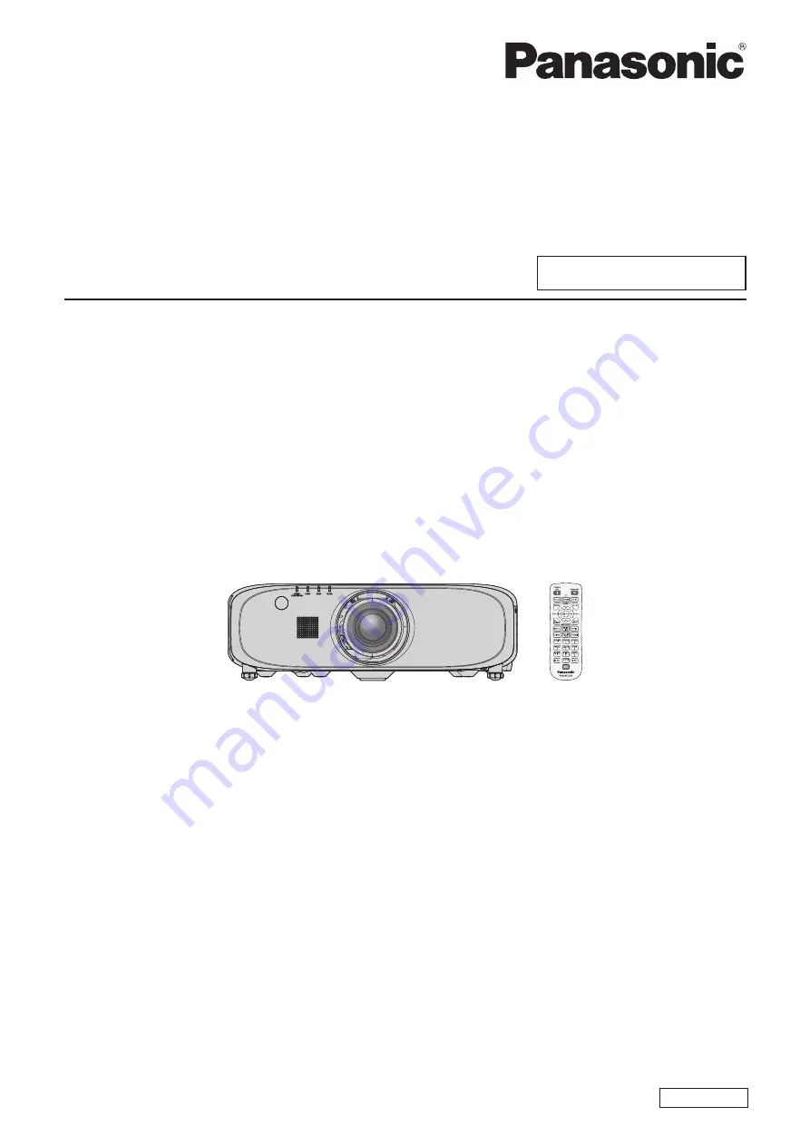
background image

Thank you for purchasing this Panasonic product.


This manual is common to all the models regardless of suffixes of the Model No.


z

Without L  : The standard zoom lens supplied 

With L  : The lens sold separately


Before operating this product, please read the instructions carefully and save this manual 

for future use.


Before using this product, be sure to read “Read this first!” (

x

 pages 2 to 11).

TQBJ0636

LCD Projector  

Commercial Use

Operating Instructions

Functional Manual

ENGLISH

Model No. 

PT-EZ770Z


PT-EW730Z


PT-EX800Z

Summary of Contents for PT-EW730Z

Page 1: ...zoom lens supplied With L The lens sold separately Before operating this product please read the instructions carefully and save this manual for future use Before using this product be sure to read Read this first x pages 2 to 11 TQBJ0636 LCD Projector Commercial Use Operating Instructions Functional Manual ENGLISH Model No PT EZ770Z PT EW730Z PT EX800Z ...

Page 2: ...cket contact an electrician Do not defeat the purpose of the earthing plug WARNING This is a class A product In a domestic environment this product may cause radio interference in which case the user may be required to take adequate measures CAUTION To assure continued compliance follow the attached installation instructions This includes using the provided power cord and shielded interface cables...

Page 3: ...g Do not remove WARNING USA and Canada f f Not for use in a computer room as defined in the Standard for the Protection of Electronic Computer Data Processing Equipment ANSI NFPA 75 f f For permanently connected equipment a readily accessible disconnect device shall be incorporated in the building installation wiring f f For pluggable equipment the socket outlet shall be installed near the equipme...

Page 4: ... A digital device pursuant to part 15 of the FCC Rules These limits are designed to provide reasonable protection against harmful interference when the equipment is operated in a commercial environment This equipment generates uses and can radiate radio frequency energy and if not installed and used in accordance with the instruction manual may cause harmful interference to radio communications Op...

Page 5: ...new plug is to be fitted please observe the wiring code as shown below If in any doubt please consult a qualified electrician WARNING THIS APPLIANCE MUST BE EARTHED IMPORTANT The wires in this mains lead are coloured in accordance with the following code Green and Yellow Earth Blue Neutral Brown Live As the colours of the wire in the mains lead of this appliance may not correspond with the coloure...

Page 6: ...he provided power cord Failure to observe this will result in fire or electric shocks Please note that if you do not use the provided power cord to ground the device on the side of the outlet this may result in electric shocks Clean the power plug regularly to prevent it from becoming covered in dust Failure to observe this will cause a fire f f If dust builds up on the power plug the resulting hu...

Page 7: ...ay from the projector Never attempt to remodel or disassemble the projector High voltages can cause fire or electric shocks f f For any inspection adjustment and repair work please contact an Authorized Service Center Do not project an image with the lens cover attached Doing so can cause fire Do not allow metal objects flammable objects or liquids to enter inside of the projector Do not allow the...

Page 8: ...ontact with your eyes could result in loss of sight In this case do not rub your eyes Rinse with clean water and seek medical advice immediately Do not remove unspecified screws during the lamp unit replacement Doing so can cause electric shocks burns or injury Do not disassemble the lamp unit If the lamp breaks it could cause injury Lamp replacement The lamp has high internal pressure If improper...

Page 9: ...r is being used Doing so can cause damage and burns to clothing f f Extremely strong light is emitted from the projector s lens Do not place objects in front of the lens while the projector is being used Doing so can cause damage to the object and can cause the set to malfunction f f Extremely strong light is emitted from the projector s lens Always disconnect all cables before moving the projecto...

Page 10: ...you clean the air filter units dry them thoroughly before reattaching them Ask your dealer about cleaning inside the projector once a year Continuous use while dust is accumulated inside the projector may result in fire f f For cleaning fee ask your dealer To remove the battery Remote Control Battery 1 Press the guide and lift the cover ii i 2 Remove the batteries ...

Page 11: ...o pela bateria pode irritar a garganta danificar o lacre do invólucro ou o vazamento provocar calor ruptura da blindagem e produzir fogo devido ao curto circuito dos terminais Não incinere nem aqueça as baterias elas não podem ficar expostas a temperaturas superiores a 100 C 212 F O gás liberado pela bateria pode irritar a garganta danificar o lacre do invólucro ou o vazamento provocar calor ruptu...

Page 12: ...ew are registered trademarks of Crestron Electronics Inc Crestron ConnectedTM and Fusion RV are trademarks of Crestron Electronics Inc f f Adobe Adobe Flash Player and Adobe Reader are trademarks or registered trademarks of Adobe Systems Inc in the United Stated and or other countries f f Some of the fonts used in the on screen menu are Ricoh bitmap fonts which are manufactured and sold by Ricoh C...

Page 13: ...he target for replacement and not the warranty time Energy conservation achieved through the ECO function Lamp power is optimized according to the input image 1 Power consumption is also reduced by optimizing the lamp power according to the brightness of the setup installation location state of the input signals and state of the video mute 2 1 When LAMP POWER is set to AUTO 2 When ECO MANAGEMENT i...

Page 14: ...nt 43 Connecting example Computers 44 Connecting example Twisted pair cable transmitter 45 Chapter 3 Basic Operations Switching on off the projector 47 Connecting the power cord 47 Power indicator 47 Switching on the projector 48 Making adjustments and selections 48 Switching off the projector 49 Direct power off function 50 Projecting 51 Selecting the input signal 51 Adjusting the focus zoom and ...

Page 15: ...JECTION METHOD 88 ECO MANAGEMENT 89 SCHEDULE 90 STARTUP INPUT SELECT 92 RS 232C 92 REMOTE2 MODE 94 FUNCTION BUTTON 94 AUDIO SETTING 94 STATUS 96 DATE AND TIME 97 SAVE ALL USER DATA 98 LOAD ALL USER DATA 98 INITIALIZE 98 SERVICE PASSWORD 99 P IN P menu 100 Using P IN P function 100 TEST PATTERN menu 102 TEST PATTERN 102 SIGNAL LIST menu 103 Registering new signals 103 Renaming the registered signal...

Page 16: ...ooting 136 Chapter 6 Appendix Technical information 139 PJLink protocol 139 Control commands via LAN 140 SERIAL IN terminal 142 REMOTE 2 IN terminal 145 Two window display combination list 146 MENU LOCK PASSWORD operations 147 List of compatible signals 148 Specifications 151 Dimensions 154 Precautions for Ceiling Mount Bracket 155 Index 156 ...

Page 17: ...ENGLISH 17 Chapter 1 Preparation This chapter describes things you need to know or check before using the projector ...

Page 18: ...Places with sharp temperature fluctuations such as near lights studio lamps Doing so may shorten the life of the lamp or result in deformation of the outer case due to heat which may cause malfunctions The operating environment temperature of the projector should be between 0 C 32 F and 45 C 113 F when using it at elevations lower than 1 400 m 4 593 above sea level and between 0 C 32 F and 40 C 10...

Page 19: ...other than the floor standing installation using the adjustable feet fix the projector using the four screw holes for ceiling mount as shown in the figure Screw diameter M6 tapping depth inside the set 12 mm 15 32 torque 4 0 5 N m Prevent a gap forming between the setting surface and the screw holes for ceiling mount on the projector bottom for example by inserting spacers metallic between them Sc...

Page 20: ...sword for the web control and restrict the users who can log in DIGITAL LINK DIGITAL LINK is a technology that uses a twisted pair cable to transmit video audio Ethernet and serial control signals The projector supports the optional Digital Interface Box Model No ET YFB100G and the XTP transmitter of Extron Electronics For the twisted pair cable transmitter of other manufacturers of which the oper...

Page 21: ... burst with a loud sound or have its service life shortened because of shock chipping or degradation due to cumulative runtime f f The lamp life varies greatly depending on individual differences and usage conditions In particular continuous use for 12 hours or more and frequent off on switching of the power greatly deteriorate the lamp and affects the lamp life f f In rare cases the lamps burst s...

Page 22: ...perly f f Do not use the supplied power cord for devices other than this projector f f For missing accessories consult your dealer f f Store small parts in an appropriate manner and keep them away from small children Note f f The type and number of the supplied power cords vary depending on the country where you purchased the product f f The model numbers of accessories are subject to change witho...

Page 23: ...gos to be displayed when projection starts to the projector Optional accessories Optional accessories product name Model No Projection Lens Zoom lens ET ELW20 ET ELT20 ET ELT21 Fixed focus lens ET ELW21 Ceiling Mount Bracket ET PKE200H for High Ceilings ET PKE200S for Low Ceilings ET PKE200B Projector Mount Base Replacement Lamp Unit ET LAE300 Replacement Filter Unit ET RFE300 Digital Interface Bo...

Page 24: ...ENU button to proceed to the initial setting Initial setting display language Select the language to show on the screen After completed the initial setting you can change the display language from the DISPLAY LANGUAGE menu 1 Press as to select the display language ENTER 1 4 Please select DISPLAY LANGUAGE INITIAL SETTING SELECT SET 2 Press the ENTER button to proceed to the initial setting Initial ...

Page 25: ...ECTOR SETUP menu INITIALIZE is executed the setting of STANDBY MODE before execution is displayed Initial setting screen setting Set the screen format aspect ratio and display position of the image After completed the initial setting you can change the settings of each item from the DISPLAY OPTION menu SCREEN SETTING 1 Press as to select an item 2 Press qw to switch the setting 16 10 4 4 SCREEN PO...

Page 26: ...gle remote control when using multiple projectors x page 30 11 ECO button Displays the setting screen relating to ECO management x pages 57 89 12 SHUTTER button Used when temporarily turning off the image and audio x page 53 13 AUTO SETUP button Automatically adjusts the image display position while the image is projected PROGRESS is displayed on the screen while adjusting automatically x page 55 ...

Page 27: ...or ON G STANDBY R will flash if the projector receives a remote control signal Projector body 1 2 3 4 5 6 7 8 6 9 11 15 12 14 13 15 17 9 16 10 Front Side Rear Projection direction WARNING Keep your hands and other objects away from the air exhaust port f f Keep your hands and face away f f Do not insert your fingers f f Keep heat sensitive objects away Heated air from the air exhaust port can caus...

Page 28: ...ower is switched off standby mode 2 MENU button Displays or hides the main menu x page 59 Returns to the previous menu when a sub menu is displayed If you press the MENU button on the control panel for at least three seconds while the on screen display is off hidden the on screen display is turned on 3 VOL button VOL button Adjusts the volume of audio output x page 54 4 SHUTTER button Used when te...

Page 29: ...ignals or YCBCR YPBPR signals 6 RGB 2 IN R PR VIDEO G Y B PB C SYNC HD VD terminal This is the terminal to input RGB signals or YCBCR YPBPR signals Y C signals and video signals 7 DVI D IN terminal This is the terminal to input DVI D signals 8 DisplayPort IN terminal This is the terminal to input DisplayPort signals 9 VIDEO IN terminal This is the terminal to input video signals 10 AUDIO IN 1 term...

Page 30: ...ctor by pressing the ID ALL button on the remote control even if you do not know the projector ID How to set 1 Press the ID SET button on the remote control 2 Within five seconds press the two digit ID number set on the projector using the number 0 9 buttons f f If you press the ID ALL button you can control the projectors regardless of the ID number setting of the projector Attention f f Since th...

Page 31: ... jack cable The remote control is effective even in places where an obstacle stands in the light path or where devices are susceptible to outside light Connecting terminals M3 stereo mini jack cable commercially available Remote control Connecting to the remote control wired terminal Attention f f Use a cable that is 15 m 49 3 or shorter with dual core shielded The remote control may not operate w...

Page 32: ...32 ENGLISH Chapter 2 Getting Started This chapter describes things you need to do before using the projector such as the setup and connections ...

Page 33: ... on a desk floor and projecting forward Menu item Method Menu item Method PROJECTION METHOD REAR CEILING PROJECTION METHOD FRONT FLOOR Parts for ceiling mount optional You can install the projector on the ceiling using the optional Ceiling Mount Bracket Model No ET PKE200H for High Ceilings ET PKE200S for Low Ceilings and ET PKE200B Projector Mount Base f f Be sure to use the Ceiling Mount Bracket...

Page 34: ...hat the projected image size and position have been aligned to fit full inside the screen Unit m L LW LT 1 Projection distance L1 Lens protrusion dimension SH Image height SW Image width H Distance from the lens center to the lower edge of the projected image SD Projected image size 1 LW Minimum projection distance when the Zoom Lens is used LT Maximum projection distance when the Zoom Lens is use...

Page 35: ...2 69 1 The throw ratio is based on the value during projection with the projected image size of 2 03 m 80 2 When the fixed focus lens Model No ET ELW21 is attached the lens shift is not possible The height position H becomes SH 2 r r When the screen aspect ratio is 16 9 Unit m Lens type Standard zoom lens Optional lens Height position H 2 Fixed focus lens Short focus zoom lens Long focus zoom lens...

Page 36: ...hen the fixed focus lens Model No ET ELW21 is attached the lens shift is not possible The height position H becomes SH 2 For PT EW730Z r r When the screen aspect ratio is 16 10 Unit m Lens type Standard zoom lens Optional lens Height position H 2 Fixed focus lens Short focus zoom lens Long focus zoom lens Ultra long focus zoom lens Projection Lens Model No ET ELW21 ET ELW20 ET ELT20 ET ELT21 Stand...

Page 37: ... When the fixed focus lens Model No ET ELW21 is attached the lens shift is not possible The height position H becomes SH 2 r r When the screen aspect ratio is 4 3 Unit m Lens type Standard zoom lens Optional lens Height position H 2 Fixed focus lens Short focus zoom lens Long focus zoom lens Ultra long focus zoom lens Projection Lens Model No ET ELW21 ET ELW20 ET ELT20 ET ELT21 Standard zoom lens ...

Page 38: ...03 m 80 2 When the fixed focus lens Model No ET ELW21 is attached the lens shift is not possible The height position H becomes SH 2 r r When the screen aspect ratio is 16 9 Unit m Lens type Standard zoom lens Optional lens Height position H 2 Fixed focus lens Short focus zoom lens Long focus zoom lens Ultra long focus zoom lens Projection Lens Model No ET ELW21 ET ELW20 ET ELT20 ET ELT21 Standard ...

Page 39: ...534 4 3 Min LW L 1 1952 x SD 0 0555 Max LT L 1 6273 x SD 0 0534 Long focus zoom lens ET ELT20 16 10 Min LW L 2 3662 x SD 0 1140 Max LT L 3 8583 x SD 0 1129 16 9 Min LW L 2 4320 x SD 0 1140 Max LT L 3 9656 x SD 0 1129 4 3 Min LW L 2 6788 x SD 0 1140 Max LT L 4 3680 x SD 0 1129 Ultra long focus zoom lens ET ELT21 16 10 Min LW L 3 8667 x SD 0 2123 Max LT L 6 1416 x SD 0 2108 16 9 Min LW L 3 9742 x SD...

Page 40: ...0 0540 16 9 Min LW L 1 1024 x SD 0 0558 Max LT L 1 5013 x SD 0 0540 Long focus zoom lens ET ELT20 4 3 Min LW L 2 2693 x SD 0 1142 Max LT L 3 7031 x SD 0 1129 16 9 Min LW L 2 4724 x SD 0 1142 Max LT L 4 0346 x SD 0 1129 Ultra long focus zoom lens ET ELT21 4 3 Min LW L 3 7091 x SD 0 2132 Max LT L 5 8937 x SD 0 2109 16 9 Min LW L 4 0339 x SD 0 2132 Max LT L 6 4212 x SD 0 2109 Adjusting adjustable fee...

Page 41: ... remove the lens hole cover only lens options models and lens cover attached to the Projection Lens Removing the Projection Lens Remove the Projection Lens with the following procedure iii i ii Projection Lens Lens release button 1 With the lens release button held down turn the Projection Lens counterclockwise to the end and remove the Projection Lens Attention f f Store the removed Projection Le...

Page 42: ... a time base corrector TBC must be connected f f The projector accepts video signals Y C signals YCBCR YPBPR signals analog RGB signals synchronization signals are TTL level and digital signals f f Some computer models or graphics cards are not compatible with the projector f f Use a cable compensator when you connect devices to the projector using long cables Otherwise the image may not display p...

Page 43: ... 24 16 9 1 8 1 T M D S data 2 13 2 T M D S data 2 14 5 V 3 T M D S data 2 4 shield 15 GND 4 16 Hot plug detection 5 17 T M D S data 0 6 DDC clock 18 T M D S data 0 7 DDC data 19 T M D S data 0 5 shield 8 20 9 T M D S data 1 21 10 T M D S clock1 22 T M D S clock shield 11 T M D S data 1 3 shield 23 T M D S clock 12 24 T M D S clock Connecting example AV equipment Audio device Blu ray disc player DV...

Page 44: ...l device use the power cord supplied with each device and commercially available shielded cables Note f f When entering DVI D some external devices to be connected may require switching the setting using the DISPLAY OPTION menu DVI D IN EDID f f For an HDMI cable use an HDMI High Speed cable that conforms to HDMI standards If a cable that does not conform to HDMI standards is used images may be in...

Page 45: ...g to the projector using a twisted pair cable transmitter receiver of other manufacturer do not place another twisted pair cable transmitter between the twisted pair cable transmitter of other manufacturer and the projector This may cause image and sound to be disrupted f f Do not pull cables forcefully Also do not bend or fold cables unnecessarily f f To reduce the effects of noise as much as pos...

Page 46: ...46 ENGLISH Chapter 3 Basic Operations This chapter describes basic operations to start with ...

Page 47: ...1 Confirm that the MAIN POWER switch on the rear of the projector body is on the OFF side and remove the power plug from the outlet 2 Remove the power cord connector from the AC IN terminal of the projector body while pressing the side tabs Power indicator Displays the status of the power Check the ON G STANDBY R status of the power indicator before operating the projector Power indicator ON G STA...

Page 48: ...o the projector body 2 Connect the power plug to an outlet f f AC 100 V 240 V 50 Hz 60 Hz 3 Press the ON side of the MAIN POWER switch to turn on the power f f After a short while the power indicator ON G STANDBY R will light in red and the projector will enter the standby mode 4 Press the power v b button on the control panel or the power on b button on the remote control f f The power indicator ...

Page 49: ...er standby v button on the remote control f f The POWER OFF STANDBY confirmation screen is displayed 2 Press qw to select OK and press the ENTER button Or press the power v b button on the control panel or the power standby v button on the remote control again f f Projection of the image will stop and the power indicator ON G STANDBY R on the projector body lights in orange The fan keeps running 3...

Page 50: ...eaker It is also safe in case a power outage occurs or the power cord is pulled out immediately after the projector is switched off Note f f If the projector was turned off by turning off the circuit breaker directly during projection last time then the power indicator ON G STANDBY R will light in green a while after the circuit breaker is turned on and then projection of the image will start f f ...

Page 51: ...anel 1 Press the LENS button on the control panel f f Pressing the button changes the adjustment screen in the order of FOCUS ZOOM and SHIFT 2 Select each item and press asqw to adjust it Using the remote control 1 Press the lens FOCUS ZOOM SHIFT buttons on the remote control f f FOCUS button Adjusts focus f f ZOOM button Adjusts zoom f f SHIFT button Adjusts shift 2 Select each item and press asq...

Page 52: ...isplay the HOME POSITION screen by pressing the LENS button on the control panel or the SHIFT button on the remote control for at least three seconds Adjustment range by the lens position shift optical shift Perform the lens position shift within the adjustment range The focus may change when the lens position is shifted out of the adjustment range This is because the movement of the lens is restr...

Page 53: ...DMI Note f f When the optional Digital Interface Box Model No ET YFB100G is connected to the DIGITAL LINK LAN terminal the ET YFB100G input changes with each press of the DIGITAL LINK button The input can also be changed using the control command of RS 232C For twisted pair cable transmitters of other manufacturers switch the input on the projector to DIGITAL LINK and then switch the input on the ...

Page 54: ...ontrol f f This operation can be also performed using the VOL button VOL button on the control panel VOL Increases the volume VOL Decreases the volume Using the freeze function The projected image can be paused and audio turned off regardless of the playback of the external device button 1 Press the FREEZE button f f The image freezes and audio disappears 2 Press the FREEZE button again f f Freezi...

Page 55: ...nd computer graphics button 1 Press the AUTO SETUP button f f COMPLETE is displayed when it has completed without any problem Note f f The clock phase may shift even if it has completed without any incident In such cases adjust the POSITION menu CLOCK PHASE x page 72 f f If an image with blurred edges or a dark image is input INCOMPLETE may appear or adjustment may not be performed properly even w...

Page 56: ...for the next corner is displayed f f Refer to the POSITION menu KEYSTONE x page 72 for details Using the digital zoom function The DIGITAL ZOOM menu can be displayed You can enlarge images button 1 Press the D ZOOM button f f The DIGITAL ZOOM screen is displayed 2 Press qw to adjust the magnification 3 Press the ENTER button 4 Press asqw to move the zoom position Note f f Refer to the DISPLAY OPTI...

Page 57: ...can display the status of the projector button 1 Press the STATUS button f f The STATUS screen is displayed RGB2 SXGA60 A1 65 22kHz 59 99Hz 1h 100h 200h 300h 27 C 80 F 27 C 80 F 1 4 MENU ENTER EXIT CHANGE SEND STATUS VIA E MAIL AROUND LAMP TEMP INTAKE AIR TEMP TOTAL NORMAL LAMP ECO PROJECTOR RUNTIME SIGNAL FREQUENCY SIGNAL NAME INPUT STATUS Note f f This can be displayed from the PROJECTOR SETUP m...

Page 58: ...58 ENGLISH Chapter 4 Settings This chapter describes the settings and adjustments you can make using the on screen menu ...

Page 59: ...ISPLAY LANGUAGE DISPLAY OPTION PROJECTOR SETUP P IN P TEST PATTERN SIGNAL LIST SECURITY NETWORK MENU SELECT SUB MENU ENTER 2 Press as to select an item from the main menu f f The selected item is highlighted in yellow MAIN MENU PICTURE POSITION ADVANCED MENU DISPLAY LANGUAGE DISPLAY OPTION PROJECTOR SETUP P IN P TEST PATTERN SIGNAL LIST SECURITY NETWORK MENU SELECT SUB MENU ENTER 3 Press the ENTER...

Page 60: ...N SCREEN DISPLAY OSD DESIGN The selected item is displayed with the yellow cursor by the factory default Resetting adjustment values to the factory defaults If the DEFAULT button on the remote control is pressed the values adjusted in the menu items are restored to the factory default settings button 1 Press the DEFAULT button on the remote control 0 CONTRAST ADJUST Note f f You cannot reset all t...

Page 61: ...NOISE REDUCTION OFF 67 IRIS OFF 1 67 DAYLIGHT VIEW AUTO 68 SYSTEM SELECTOR YPBPR 1 68 1 Depends on the signal input Note f f The factory default settings may vary depending on the picture mode POSITION Sub menu item Factory default Page SHIFT 70 ASPECT NORMAL 1 70 ZOOM 71 CLOCK PHASE 0 1 72 KEYSTONE 72 1 Depends on the signal input ADVANCED MENU Sub menu item Factory default Page DIGITAL CINEMA RE...

Page 62: ...3 BACK COLOR BLUE 84 STARTUP LOGO DEFAULT LOGO 84 SHUTTER SETTING 84 P TIMER 85 FREEZE 86 DIGITAL ZOOM 1 5 86 PROJECTOR SETUP Sub menu item Factory default Page PROJECTOR ID ALL 88 PROJECTION METHOD FRONT FLOOR 88 ECO MANAGEMENT 89 SCHEDULE OFF 90 STARTUP INPUT SELECT LAST USED 92 RS 232C 92 REMOTE2 MODE DEFAULT 94 FUNCTION BUTTON 94 AUDIO SETTING 94 STATUS 96 DATE AND TIME 97 SAVE ALL USER DATA 9...

Page 63: ...tory default Page DIGITAL LINK MODE AUTO 109 DIGITAL LINK SETUP 109 DIGITAL LINK STATUS 110 NETWORK SETUP 110 NETWORK CONTROL 111 NETWORK STATUS 111 DIGITAL INTERFACE BOX 111 Note f f Some items may not be adjusted or used for certain signal formats to be input to the projector The menu items that cannot be adjusted or used are shown in black characters and they cannot be selected f f Sub menu ite...

Page 64: ...The image becomes suitable for movie contents NATURAL 2 The image is sRGB compliant 1 Only for movie based input signals 2 Only for still image input signals Note f f The factory default picture mode is DYNAMIC for still image input signals and STANDARD for movie based input signals f f When PICTURE MODE is set to DICOM SIM LAMP POWER x page 89 is fixed to NORMAL f f DICOM is an abbreviation of Di...

Page 65: ...ne in the projected image 1 Press as to select TINT 2 Press qw or the ENTER button f f The TINT individual adjustment screen is displayed 3 Press qw to adjust the level Operation Adjustment Range of adjustment Press the w button Adjusts skin tone toward greenish color 31 31 Press the q button Adjusts skin tone toward reddish purple COLOR TEMPERATURE You can switch the color temperature if the whit...

Page 66: ...ess the q button Weakens red GREEN Press the w button Deepens green Press the q button Weakens green BLUE Press the w button Deepens blue Press the q button Weakens blue Note f f Adjust COLOR TEMPERATURE correctly All colors will not be displayed properly unless adequate adjustment is made If the adjustment does not look suitable you can press the DEFAULT button on the remote control to return the...

Page 67: ...f you press w while the adjustment value is 15 the value will become 0 If you press q while the adjustment value is 0 the value will become 15 NOISE REDUCTION You can reduce noises when the input image is degraded and noise is occurring in the image signal 1 Press as to select NOISE REDUCTION 2 Press qw or the ENTER button f f The NOISE REDUCTION individual adjustment screen is displayed 3 Press q...

Page 68: ... can set the system method manually when an unstable signal is input Set the system method matching the input signal 1 Press as to select SYSTEM SELECTOR 2 Press the ENTER button 3 Press as to select a system format f f Available system formats vary depending on the input signal Terminal System format VIDEO IN terminal VIDEO G Y B PB C terminals Select AUTO NTSC NTSC4 43 PAL PAL M PAL N SECAM or P...

Page 69: ... 77 2 Set COLOR CORRECTION to OFF f f Refer to COLOR CORRECTION x page 77 3 Display the PICTURE menu f f Refer to PICTURE menu x page 64 4 Press as to select PICTURE MODE 5 Press qw to set NATURAL 6 Press as to select COLOR 7 Press the DEFAULT button on the remote control to set the factory default setting 8 Follow Steps 6 7 to set TINT COLOR TEMPERATURE and GAMMA to the factory default settings 9...

Page 70: ...w to adjust the position Orientation Operation Adjustment Vertical up and down adjustment Press the a button The image position moves up Press the s button The image position moves down Horizontal right and left adjustment Press the w button The image position moves to the right Press the q button The image position moves to the left ASPECT You can switch the aspect ratio of the image The aspect r...

Page 71: ...AT 1 For video signals NTSC and Y C signals NTSC only 2 During RGB signal 480i 480p input 3 Standard signals are input signals with an aspect ratio of 4 3 or 5 4 4 Wide screen signals are input signals with an aspect ratio of 16 10 16 9 15 9 or 15 10 Note f f Some size modes are not available for certain types of input signals NORMAL cannot be selected for video signal NTSC Y C signal NTSC and RGB...

Page 72: ...SE 2 Press qw or the ENTER button f f The CLOCK PHASE individual adjustment screen is displayed 3 Press qw to adjust f f Adjustment value will change between 0 and 31 Adjust so that the amount of interference is at a minimum Note f f Certain signals may not be adjustable f f Optimal value may not be achieved if the output from the input computer is unstable f f Optimal value may not be achieved wh...

Page 73: ...tton is pressed on the remote control while the KEYSTONE or CORNER CORRECTION screen is displayed the screen will be switched to the other adjustment screen f f Pressing the ENTER button while the CORNER CORRECTION individual adjustment screen is displayed will also display the individual adjustment screen for the next corner f f Correcting up to 40 for the tilt in the vertical direction maximum v...

Page 74: ... 2 pulldown 25p FIXED Only during 576i or 1080 50i signal input Note f f In DIGITAL CINEMA REALITY the picture quality will degrade when a signal other than the 2 2 pulldown is set as 25p FIXED or 30p FIXED Vertical resolution will degrade BLANKING You can adjust the blanking width if there are noises at the edge of the screen or the image is slightly running out from the screen while an image fro...

Page 75: ...al stripes or sections are missing from the screen Note f f Previously mentioned vertical banding will not occur with all white signal input f f INPUT RESOLUTION can be adjusted only when an RGB signal is input to the RGB 1 IN terminal or the RGB 2 IN terminal f f Certain signals may not be adjustable CLAMP POSITION You can adjust the optimal point when the black part of the image is blunt or it h...

Page 76: ...tton to set Changing the display language You can select the language of the on screen display ENTER DISPLAY LANGUAGE SELECT SET f f Various menus settings adjustment screens control button names etc are displayed in the selected language f f The language can be changed to English German French Spanish Italian Portuguese Japanese Chinese Russian or Korean Note f f The on screen display language of...

Page 77: ...as to select RED GREEN or BLUE 7 Press qw to adjust f f The adjustment value changes between 0 1 and 2 048 1 The lower limit varies depending on the adjusting color Note f f Operation when correcting the adjustment color When the correction color same as the adjustment color is changed The luminance of the adjustment color changes When correction color red is changed Red is added to or subtracted ...

Page 78: ... 3 Cannot be adjusted 16 9 Adjusts the vertical position between 96 and 96 4 Press as to select SCREEN POSITION f f If SCREEN FORMAT is set to 16 10 on PT EZ770Z PT EW730Z or SCREEN FORMAT is set to 4 3 on PT EX800Z then selection and adjustment of SCREEN POSITION are not available 5 Press qw to adjust SCREEN POSITION AUTO SIGNAL Set whether to execute automatic setup of signals automatically The ...

Page 79: ...ADJUST 4 Press qw to switch the item ON Adjust the screen position and size when automatic setup is executed OFF Does not perform automatic adjustment Adjusting signal level automatically 1 Press as to select AUTO SETUP 2 Press the ENTER button f f The AUTO SETUP screen is displayed 3 Press as to select SIGNAL LEVEL ADJUST 4 Press qw to switch the item OFF Does not perform automatic adjustment ON ...

Page 80: ...nnected to the DVI D IN terminal EDID2 PC Select mainly when an external device that outputs still image video signals such as a computer is connected to the DVI D IN terminal 5 Press as to select SIGNAL LEVEL 6 Press qw to switch the item f f The items will switch each time you press the button AUTO Automatically sets the signal level 0 255 PC Select when the DVI D terminal output of an external ...

Page 81: ...ted pair cable transmitter 0 1023 Select when the DVI D terminal output or HDMI terminal output of an external device such as a computer is connected to the DIGITAL LINK LAN terminal via a twisted pair cable transmitter Note f f The optimal setting varies depending on the output setting of the connected external device Refer to the operating instructions of the external device regarding the output...

Page 82: ...een is displayed 3 Press as to select OSD DESIGN 4 Press qw to switch the item f f The items will switch each time you press the button 1 Sets to yellow 2 Sets to blue 3 Sets to white 4 Sets to green 5 Sets to peach 6 Sets to brown Setting OSD MEMORY Set hold for the position of the menu screen OSD cursor 1 Press as to select ON SCREEN DISPLAY 2 Press the ENTER button f f The ON SCREEN DISPLAY scr...

Page 83: ... NTSC or 480i YCBCR signal input only Set closed captions Selecting the closed caption display 1 Press as to select CLOSED CAPTION SETTING 2 Press the ENTER button f f The CLOSED CAPTION SETTING screen is displayed 3 Press as to select CLOSED CAPTION 4 Press qw to switch the item f f The items will switch each time you press the button OFF Hides closed captions ON Displays closed captions f f When...

Page 84: ...splays the entire projection area in black DEFAULT LOGO Displays the Panasonic logo USER LOGO Displays the image registered by the user Note f f To create register the USER LOGO image use Logo Transfer Software included in the supplied CD ROM STARTUP LOGO Set the logo display when the power is turned on 1 Press as to select STARTUP LOGO 2 Press qw to switch the item f f The items will switch each ...

Page 85: ... Displays the remaining time of the time set by TIMER Setting the timer 1 Press as to select P TIMER 2 Press the ENTER button f f The P TIMER screen is displayed 3 Press as to select TIMER 4 Press qw to set the time f f The time can be set in 1 minute increments from 1 to 180 minutes f f The factory default value is 10 minutes Note f f TIMER is enabled when MODE is set to COUNT DOWN Using the pres...

Page 86: ...UNT UP is set and turns counterclockwise when COUNT DOWN is set Ending the presentation timer 1 Press as to select P TIMER 2 Press the ENTER button f f The P TIMER screen is displayed 3 Press as to select EXIT 4 Press the ENTER button FREEZE The projected image is paused and audio turned off regardless of the playback of the external device 1 Press as to select FREEZE 2 Press the ENTER button f f ...

Page 87: ...0x and 2 0x For some computer signals the magnification can be adjusted up to 3 0x f f The digital zoom function is canceled if the MENU button is pressed during a digital zoom f f The digital zoom function is canceled if the input signal changes during a digital zoom f f During a digital zoom the freeze function is disabled ...

Page 88: ...ied during remote control or computer control If multiple projectors are set up side by side with IDs set to ALL they cannot be controlled separately from the projectors with other ID numbers f f Refer to Setting the ID number of the remote control x page 30 for how to set the ID number on the remote control PROJECTION METHOD Set the projection method in accordance with the installation status of ...

Page 89: ...R cannot be set LAMP POWER is fixed to NORMAL Setting AUTO POWER SAVE Set whether or not to enable the three functions AMBIENT LIGHT DETECTION SIGNAL DETECTION and SHUTTER DETECTION 1 Press as to select ECO MANAGEMENT 2 Press the ENTER button f f The ECO MANAGEMENT screen is displayed 3 Press as to select AUTO POWER SAVE 4 Press qw to switch the item f f The items will switch each time you press t...

Page 90: ...work function during standby Note f f When ECO is set the network function and some RS 232C commands become inoperable during standby When NORMAL is set the network function becomes operable during standby f f When set to ECO it may take approx 10 seconds longer before the projector starts projecting after the power is turned on compared with when NORMAL is set f f The STANDBY MODE settings are no...

Page 91: ...d press the ENTER button and then press asqw to select the input to set COMMAND Detailed settings of COMMAND Description POWER ON Switches on the projector STANDBY Enters standby SHUTTER OPEN Opens the shutter CLOSE Closes the shutter INPUT VIDEO Switches the input to VIDEO RGB1 Switches the input to RGB1 RGB2 Switches the input to RGB2 DVI D Switches the input to DVI D HDMI Switches the input to ...

Page 92: ...mmand set in SCHEDULE is executed the command set with this function may not be executed STARTUP INPUT SELECT Set the input when the projector is switched on to start projection 1 Press as to select STARTUP INPUT SELECT 2 Press the ENTER button f f The STARTUP INPUT SELECT screen is displayed 3 Press asqw to select an input f f The items will switch each time you press the button LAST USED Keeps t...

Page 93: ...6300 series D6000 series D5000 series DZ570 series DW530 series DX500 series L730 SERIES L730 series L720 series L520 series L780 SERIES L780 series L750 series L735 SERIES L735 series L785 SERIES L785 series F W SERIES FW430 series FX400 series FW300 series F300 series F200 series FW100 series F100 series LZ370 LZ370 series LB W SERIES LB3 series LB2 series LB1 series ST10 series LB90 series LW80...

Page 94: ...NCTION BUTTON 2 Press the ENTER button f f The FUNCTION BUTTON screen is displayed 3 Press as to select a function DISABLE Disables the FUNCTION button SUB MEMORY Displays the sub memory list x page 105 SYSTEM SELECTOR Switches the SYSTEM SELECTOR setting x page 68 DAYLIGHT VIEW Switches the DAYLIGHT VIEW setting x page 68 TEST PATTERN Displays the test pattern built in to the projector x page 102...

Page 95: ...vices connected to the VARIABLE AUDIO OUT terminal and not from the built in speaker set BUILT IN SP to OFF Setting audio output in the standby mode 1 Press as to select AUDIO SETTING 2 Press the ENTER button f f The AUDIO SETTING screen is displayed 3 Press as to select IN STANDBY MODE 4 Press qw to switch the item f f The items will switch each time you press the button OFF Audio is not output d...

Page 96: ...uency of the input signal PROJECTOR RUNTIME Displays the operation times of the projector LAMP ECO 1 Converts the total lamp runtime when LAMP POWER is set to ECO1 and ECO2 into the runtime when set to ECO2 and displays the converted runtime LAMP NORMAL Displays the lamp runtime when LAMP POWER is set to AUTO and NORMAL by actual time LAMP TOTAL 1 Converts the cumulative lamp runtime into the runt...

Page 97: ...B Runtime when LAMP POWER is set to ECO2 Lamp runtime displayed in LAMP TOTAL C x 3 D x 2 3 f f C Actual runtime when LAMP POWER is set to AUTO and NORMAL Runtime displayed in LAMP NORMAL f f D Actual runtime when LAMP POWER is set to ECO1 and ECO2 Runtime displayed in LAMP ECO Note f f The content of status can be sent via E mail by pressing the ENTER button while displaying the STATUS screen f f...

Page 98: ...the confirmation screen is displayed press qw to select OK and press the ENTER button f f PROGRESS is displayed while saving data Note f f Data set from the computer application is not included in ALL USER DATA LOAD ALL USER DATA Load the various setting values saved as a backup in the built in memory of the projector 1 Press as to select LOAD ALL USER DATA 2 Press the ENTER button f f The SECURIT...

Page 99: ... the procedure described in Deleting the registered signal x page 104 NETWORK E MAIL Returns NETWORK SETUP and E mail set up to factory default settings LOGO IMAGE Deletes the image registered in USER LOGO 5 Press the ENTER button 6 When the confirmation screen is displayed press qw to select OK and press the ENTER button SERVICE PASSWORD This function is used by a service person ...

Page 100: ...P MODE 2 Press the ENTER button f f The P IN P MODE screen is displayed 3 Press as to select the desired mode from USER1 USER2 and USER3 and press the ENTER button 4 Press the MENU button 5 Press as to select MAIN WINDOW or SUB WINDOW and press the ENTER button 6 Press as to select the input terminal to be displayed in the window and press the ENTER button 7 Press the MENU button 8 Press as to sel...

Page 101: ...eing input or terminals being selected Refer to Two window display combination list x page 146 for details f f The main window setting values are applied to image adjustment values such as PICTURE MODE GAMMA and COLOR TEMPERATURE f f On the normal screen when no menu is displayed press as to switch the size and position of the main window and sub window while P IN P is operating f f If the signals...

Page 102: ...f The items will switch each time you press the button Menu screen Color bar vertical Displays test patterns with the menu screen Select a test pattern so that it is easy to make various adjustments Menu screen Color bar horizontal Menu screen 16 gradations vertical 1 Menu screen 16 gradations vertical 2 Menu screen 16 gradations horizontal 1 Menu screen 16 gradations horizontal 2 Menu screen Cros...

Page 103: ...numbers f f If a menu is being displayed the new signals will be registered at the instant they are input Renaming the registered signal Registered signals can be renamed 1 Press asqw to select the signal of which name is to be changed 2 Press the ENTER button f f The REGISTERED SIGNAL STATUS screen is displayed f f The memory number input terminal input signal name frequency synch polarity etc ar...

Page 104: ...termined to be B1 f f When a registration signal is deleted the settings are also deleted f f In an environment where multiple types of signals are input to the same terminal signals are sometimes not determined correctly when the setting is set to WIDE Protecting the registered signal 1 Press asqw to select the signal to protect 2 Press the ENTER button f f The REGISTERED SIGNAL STATUS screen is ...

Page 105: ... the FUNCTION button on the remote control can be used instead of qw 2 Press asqw to select the sub memory number to register in SUB MEMORY LIST 3 Press the ENTER button f f The SIGNAL NAME CHANGE screen is displayed 4 Press asqw to select OK and press the ENTER button f f To rename the registered signal follow the procedure in Steps 6 and 7 in Renaming the registered signal x page 103 Switching t...

Page 106: ... password is incorrect the operation will be restricted to the power v b button on the control panel and the power standby v button SHUTTER button and LENS FOCUS ZOOM and SHIFT buttons on the remote control 1 Press as to select SECURITY PASSWORD 2 Press qw to switch the item f f The items will switch each time you press the button OFF Disables the security password entry ON Enables the security pa...

Page 107: ...ay the menu by the MENU button and set whether or not to enable menu operations 1 Press as to select MENU LOCK 2 Press qw to switch the item f f The items will switch each time you press the button OFF Unlocks menu operations ON Locks menu operations Note f f When the entered password is incorrect after setting MENU LOCK to ON the MENU button cannot be operated f f MENU LOCK is set to OFF at the t...

Page 108: ... remote control ENABLE Enables all button operations DISABLE Disables all button operations 6 Press the ENTER button f f The confirmation screen is displayed 7 Press qw to select OK and press the ENTER button Note f f When a button operation is performed on the device set to DISABLE the MENU LOCK PASSWORD screen is displayed Enter the menu lock password f f The MENU LOCK PASSWORD screen will disap...

Page 109: ...he communication method to Ethernet Possible communication modes Setting Communication possible Image transmission Ethernet RS 232C AUTO For DIGITAL LINK l l l For Ethernet l DIGITAL LINK l l l ETHERNET l l Communication possible Communication not possible DIGITAL LINK SETUP Set the communication method of DIGITAL LINK or Ethernet When the projector is connected directly via Ethernet 1 Press as to...

Page 110: ...OFF or ON is displayed SIGNAL QUALITY SIGNAL QUALITY is a numerical value of the amount of error and the display color changes to green yellow or red depending on that value Check the signal quality level while receiving a signal from the twisted pair cable transmitter f f MAX MIN Maximum minimum value of the amount of error f f Green 12 dB or lower Normal signal quality level f f Yellow 11 to 8 d...

Page 111: ...TRON XTP setting must be set to OFF when connecting the optional Digital Interface Box Model No ET YFB100G For details of the XTP transmitter refer to the website of Extron Electronics URL http www extron com STORE Save the current network control settings 4 Press as to select STORE and press the ENTER button 5 When the confirmation screen is displayed press qw to select OK and press the ENTER but...

Page 112: ... f f A web browser is required to use this function Confirm that the web browser can be used beforehand Compatible OS Windows XP Windows Vista Windows 7 Windows 8 Mac OS X v10 4 v10 5 v10 6 v10 7 v10 8 Compatible browser Internet Explorer 7 0 8 0 9 0 10 0 Safari 4 0 5 0 6 0 Mac OS f f Communication with an E mail server is required to use the E mail function Confirm that the E mail can be used bef...

Page 113: ... and the projector away from other cables particularly power cables f f When installing multiple cables run them side by side along the shortest distance possible without bundling them together f f After laying the cables confirm that the value of SIGNAL QUALITY in the NETWORK menu DIGITAL LINK STATUS is displayed in green indicates normal quality x page 110 f f For twisted pair cable transmitter ...

Page 114: ...hat for the model you are using Descriptions of items 1 2 3 4 5 6 1 Page tab Pages are switched by clicking this item 2 Status The status of the projector is displayed by clicking this item 3 Projector control The Projector control page is displayed by clicking this item 4 Detailed set up The Detailed set up page is displayed by clicking this item 5 Change password The Change password page is disp...

Page 115: ...y be blocked LAMP REMAIN TIME The runtime of the lamp has exceeded the specified time and it is time to replace the lamp LAMP STATUS The lamp has failed to turn on Wait a while until the luminous lamp cools off and then turn on the power APERTURE CONTRAST SHUTTER There is a problem in the contrast shutter circuit for iris Consult your dealer SHUTTER MUTE SHUTTER There is a problem with the shutter...

Page 116: ...ccess with unauthorized user names or passwords Mail error page Click Status Mail error Display E mail error information if failed to send periodic E mails Note f f Access error and Mail error display the recent few hundred accesses requests All information may not be displayed when many accesses requests are made at a time f f When information in Access error and Mail error exceeds a certain amou...

Page 117: ...ICTURE MODE Switches the picture mode 4 SHUTTER Switches the setting whether to use the shutter function closing opening of the shutter 5 POWER Turns on off the power 6 CLOSED CAPTION Switches the closed caption setting Advanced control page Click Projector control Advanced control 1 2 1 POSITION Operates field angle related settings 2 PICTURE Operates picture quality settings ...

Page 118: ...ple 192 168 0 253 7 DNS2 Enter the DNS2 server address Available characters for the entry of DNS2 server address secondary Numbers 0 9 period Example 192 168 0 254 8 Back Change Click the Back button to return to the original screen The screen for confirming the current settings is displayed by clicking the Change button Click the Submit button to update the settings Note f f When you use the Forw...

Page 119: ... NTP SERVER NAME Enter the IP address or server name of the NTP server when you set to adjust the date and time manually To enter the server name the DNS server needs to be set up 5 Date Enter the date to be changed 6 Time Enter the time to be changed 7 Set date and time Updates the date and time settings Note f f The replacement of the battery inside the projector is required when the time goes o...

Page 120: ... be sent for 60 minutes after sending the temperature warning E mail even if it reaches the warning temperature 6 INTAKE AIR TEMPERATURE Change the temperature setting for the temperature warning mail A temperature warning E mail is sent when the temperature exceeds this value 8 7 8 7 9 7 E MAIL ADDRESS 1 E MAIL ADDRESS 2 Enter the E mail address to be sent Leave E MAIL ADDRESS 2 blank when two E ...

Page 121: ... the port number of the POP server Normally 110 8 Submit Updates the settings ECO management set up page Settings related to the ECO management function of the projector can be made Click Detailed set up ECO management set up 1 7 2 3 4 5 6 1 LAMP POWER Selects the LAMP POWER setting 2 AUTO POWER SAVE Set to ON when setting AMBIENT LIGHT DETECTION SIGNAL DETECTION and SHUTTER DETECTION 3 AMBIENT LI...

Page 122: ...00 OFF 17 00 OFF 18 00 OFF 19 00 OFF 20 00 OFF 21 00 OFF 22 00 OFF 23 00 OFF check system MAIN CPU BUS OK FAN OK INTAKE AIR TEMPERATURE OK AROUND LAMP TEMPERATURE OK LAMP REMAIN TIME OK LAMP STATUS OK APERTURE CONTRAST SHUTTER OK SHUTTER MUTE SHUTTER OK INTAKE AIR TEMP SENSOR OK AROUND LAMP TEMP SENSOR OK BATTERY OK AIRFLOW SENSOR OK LENS MOUNTER OK COVER OPEN OK PRESSURE SENSOR OK ANGLE SENSOR OK...

Page 123: ... AIR FILTER OK Error code00 00 00 00 00 00 00 00 00 00 00 00 20 00 00 00 Intake air temperature 45 degC 113 degF Around lamp temperature 42 degC 107 degF PROJECTOR RUNTIME 2500 H LAMP ECO 100 H LAMP NORMAL 200 H LAMP REMAIN 1900 H Current status MAIN VERSION 1 00 NETWORK VERSION 1 00 SUB VERSION 1 00 LAMP STATUS LAMP ON INPUT SIGNAL HDMI SIGNAL NAME XGA60 SIGNAL FREQUENCY 65 4kHz 54 4Hz REMOTE2 ST...

Page 124: ...gle byte Password Enter the desired new password Up to 16 characters in single byte Password Retype Enter the desired new password again 4 OK Determines the change of password User account 1 2 3 1 Account Displays the account to change 2 New User name Enter the desired new user name Up to 16 characters in single byte Password Enter the desired new password Up to 16 characters in single byte Passwo...

Page 125: ...onnected TM button is not displayed on the web control screen The control page of Crestron ConnectedTM is displayed by clicking Crestron Connected TM It is not displayed if Adobe Flash Player is not installed on the computer used or the browser used does not support Flash In that case click Back on the control page to go back to the previous page Control page 1 2 3 4 5 6 7 1 Tools Info Help Tabs f...

Page 126: ...P Displays the current setting IpAddress Displays the current setting SubnetMask Displays the current setting DefaultGateway Displays the current setting DNSServer Displays the current setting 5 Exit Returns to the control page Info page Click Info on the control page 4 5 6 7 1 2 3 8 1 Projector Name Displays the projector name 2 Mac Address Displays the MAC address 3 Lamp Hours Displays the runti...

Page 127: ...ter 4 Settings NETWORK menu ENGLISH 127 Help page Click Help on the control page The Help Desk window is displayed 1 1 Help Desk Send receive messages to from an administrator who uses Crestron ConnectedTM ...

Page 128: ...128 ENGLISH Chapter 5 Maintenance This chapter describes methods of inspection when there are problems maintenance and replacement of the units ...

Page 129: ...33 The lamp unit is not installed A problem is detected in the lamp or the power supply for the lamp Cause f f Was REPLACE LAMP displayed when you turned on the power f f The indicator lights up when the runtime of the lamp unit reaches 2 800 hours when LAMP POWER is set to NORMAL f f Is the lamp unit attached f f Have you turned on the power again immediately after turning it off f f Some error h...

Page 130: ...erating environment temperature should be between 0 C 32 F and 40 C 104 F Note f f If the temperature indicator TEMP is still lit or flashing after taking the preceding measures ask your dealer for repair f f If you use the projector with the following function set LAMP POWER may be set to ECO2 forcibly to protect the projector when the operating environment temperature becomes 40 C 104 F or highe...

Page 131: ...causing the filter replacement message to appear on the screen and the filter indicator FILTER to light in red Attention f f Make sure to turn off the power before performing maintenance on the air filter unit f f Make sure that the projector is stable and perform the maintenance in a safe place where the unit will not be damaged even if you drop the air filter unit Removing the air filter unit Ai...

Page 132: ... order f f Push in the air filter unit securely until it clicks into place 2 Attach the air filter cover f f Perform Step 1 in Removing the air filter unit in the reverse order to close the air filter cover and push in the air filter cover securely until it clicks into place f f Use a Phillips screwdriver to firmly tighten the air filter cover fixing screw x1 Attention f f After washing the air fi...

Page 133: ...ot manufactured by Panasonic Use only specified lamp units Note f f The model numbers of accessories and optional accessories are subject to change without prior notice When to replace the lamp unit The lamp unit is a consumable component Since its brightness gradually decreases over time it is necessary to replace the lamp unit regularly The estimated duration before replacement is 3 000 hours bu...

Page 134: ...k the connector 5 Use a Phillips screwdriver to firmly tighten the lamp unit fixing screws x3 f f Make sure to attach the lamp unit securely 6 Attach the lamp cover i Perform Step 2 in the reverse order to attach the lamp cover ii Use a Phillips screwdriver to firmly tighten the lamp cover fixing screw x1 f f Make sure to attach the lamp cover slowly and securely Note f f When you replace the lamp...

Page 135: ...aintenance replacement ENGLISH 135 Note f f If you use the projector without attaching the air filter unit the filter indicator FILTER flashes in red and the message appears on the projected image for approximately 30 seconds ...

Page 136: ... control does not respond f f Are the batteries depleted f f Is the polarity of the batteries set correctly 30 f f Are there any obstructions between the remote control and the remote control signal receiver of the projector 27 f f Is the remote control being used beyond its effective operation range 27 f f Are other forms of light such as fluorescent light affecting the projection 27 f f Is the R...

Page 137: ...he projector or computer may not be operated properly 150 f f The graphics accelerator driver of the computer may need to be updated to the latest version f f Turn off and on the power of the projector and the external device f f Is a signal which is not compatible with the projector being input The DIGITAL LINK input image or sound is not output f f Are the connections between the twisted pair ca...

Page 138: ...138 ENGLISH Chapter 6 Appendix This chapter describes specifications for the projector ...

Page 139: ...e Indicates lamp errors and returns 0 2 3rd byte Indicates temperature errors and returns 0 2 4th byte Indicates cover open errors and returns 0 or 2 5th byte Indicates filter errors and returns 0 2 6th byte Indicates other errors and returns 0 2 LAMP Lamp status query xxxxxx 1st digit 1 5 digits Lamp runtime 2nd digit 0 Lamp off 1 Lamp on INST Input selection list query 11 12 21 31 32 33 34 NAME ...

Page 140: ... from the following data using MD5 algorithm f f xxxxxx yyyyy zzzzzzzz xxxxxx Administrator rights user name for the web control default user name is admin1 yyyyy Password of above administrator rights user default password is panasonic zzzzzzzz 8 byte random number obtained in Step 2 Command transmission method Transmit using the following command formats r r Transmitted data Header Data section ...

Page 141: ...L ASCII string 0x20 0 0x30 CR 0x0d Data length 9 bytes 1 byte 1 byte 1 byte f f Mode 0 Non protect mode Command transmission method Transmit using the following command formats r r Transmitted data Header Data section Termination symbol Command example 0 0x30 0 0x30 Control command ASCII string CR 0x0d Data length 1 byte 1 byte Undefined length 1 byte r r Received data Header Data section Terminat...

Page 142: ...irectly Note f f The destination of RS 232C x page 92 must be set according to the connection method f f When connecting by a DIGITAL LINK compatible device set the PROJECTOR SETUP menu ECO MANAGEMENT STANDBY MODE x page 90 to NORMAL to control the projector in standby mode When STANDBY MODE is set to ECO the projector cannot be control during standby Pin assignments and signal names D Sub 9 pin f...

Page 143: ...e lamp starts illuminating there may be a delay in response or the command may not be executed Try sending or receiving any command after 60 seconds f f When transmitting multiple commands be sure to wait until 0 5 seconds has elapsed after receiving the response from the projector before sending the next command When transmitting a command which does not need a parameter a colon is not necessary ...

Page 144: ... DVI DVI D HD1 HDMI DL1 DIGITAL LINK DP1 DisplayPort Q L Lamp cumulative runtime query Returned with 0000 to 4000 OSH Shutter 1 0 Shutter off open QSH Shutter status query 1 Shutter on closed VSE Aspect ratio switch 0 NORMAL VID AUTO AUTO 1 4 3 2 WIDE 5 NATIVE QSE Aspect ratio settings query 6 FULL 9 H FIT 10 V FIT OPP P IN P execution 0 OFF 1 USER1 QPP P IN P setting query 2 USER2 3 USER3 OCS Sub...

Page 145: ...2 Other RGB2 5 VIDEO Other VIDEO 6 HDMI Other HDMI 7 DVI D Other DVI D 8 SHUTTER OFF ON 9 RST SET Controlled by remote control Controlled by external contact Attention f f When controlling make sure to short circuit pins 1 and 9 f f When pins 1 and 9 are short circuited the following buttons on the control panel and the remote control are disabled Commands for RS 232C and network functions corresp...

Page 146: ...al 3 l a l a a a a DisplayPort input Still image signal 2 l l l l l l l Movie based signal 3 l a l a a a a Sub window DVI D HDMI DIGITAL LINK DisplayPort Main window Still image 2 Movie 3 Still image 2 Movie 3 Still image 2 Movie 3 Still image 2 Movie 3 RGB1 input Still image signal l l l l l l l l Movie based signal 1 l a l a l a l a RGB2 input Still image signal l l l l l l l l Movie based signa...

Page 147: ...Interlace signals P IN P picture in picture combination is not possible 1 480i 480p 576i 576p 720 60p 720 50p 1080 60i 1080 50i 1080 24sF 1080 24p 1080 25p 1080 30p 1080 50p 1080 60p 2 VGA 640 x 480 WUXGA 1 920 x 1 200 Non interlace signal dot clock frequency 25 MHz to 162 MHz The WUXGA signal is only compatible with VESA CVT RB Reduced Blanking signals 3 Only supports 480p 576p 720 60p 720 50p 10...

Page 148: ... 48 0 74 3 R Y D H DP 1125 1080 25p 1 920 x 1 080 28 1 25 0 74 3 R Y D H DP l l 1125 1080 30p 1 920 x 1 080 33 8 30 0 74 3 R Y D H DP 1125 1080 60p 1 920 x 1 080 67 5 60 0 148 5 R Y D H DP l l l l 1125 1080 50p 1 920 x 1 080 56 3 50 0 148 5 R Y D H DP l l l l VESA400 640 x 400 37 9 85 1 31 5 R D H DP VGA 640 x 400 31 5 70 1 25 2 R D H DP 640 x 480 31 5 59 9 25 2 R D H DP l l l l l l 640 x 480 35 0...

Page 149: ...00 46 3 50 0 97 0 R D H DP 1 600 x 900 55 9 60 0 119 0 R D H DP l l l l l UXGA60 1 600 x 1 200 75 0 60 0 162 0 R D H DP l l l l l WSXGA 1 680 x 1 050 54 1 50 0 119 5 R D H DP 1 680 x 1 050 65 3 60 0 146 3 R D H DP 1920 x 1080 1 920 x 1 080 55 6 49 9 141 5 R D H DP 1 920 x 1 080 4 66 6 59 9 138 5 R D H DP 1 920 x 1 080 6 67 2 60 0 173 0 R WUXGA 1 920 x 1 200 61 8 49 9 158 3 R D H DP 1 920 x 1 200 4...

Page 150: ...playPort the projector or computer may not be operated properly when the signal output from DisplayPort on the computer is input to the projector In such a case switch off the projector or computer and then switch it on If the signal output from DisplayPort is input to the projector use of the computer equipped with the latest chipset or graphics card is recommended ...

Page 151: ... POWER is set to AUTO Color system 7 standards NTSC NTSC4 43 PAL PAL N PAL M SECAM PAL60 Projected image size 1 02 m 40 10 16 m 400 Screen aspect ratio PT EZ770Z PT EW730Z 16 10 PT EX800Z 4 3 Projection method FRONT CEILING FRONT FLOOR REAR CEILING REAR FLOOR Speaker 3 7 cm round x 1 Max effective audio output 10 W monaural Power cord length 3 0 m 118 1 8 Outer case Molded plastic Dimensions Width...

Page 152: ... 60 Hz f f 1125 1035 60i Horizontal 33 75 kHz Vertical 60 Hz f f 1125 1080 50i Horizontal 28 13 kHz Vertical 50 Hz f f 1125 1080 24sF Horizontal 27 kHz Vertical 48 Hz f f 1125 1080 30p Horizontal 33 75 kHz Vertical 30 Hz f f 1125 1080 50p Horizontal 56 25 kHz Vertical 50 Hz f f 625i 576i Horizontal 15 63 kHz Vertical 50 Hz f f 625p 576p Horizontal 31 25 kHz Vertical 50 Hz f f 750 720 50p Horizonta...

Page 153: ...ignal Y 1 0 V p p including synchronization signal PBPR 0 7 V p p 75 Ω DVI D IN terminal 1 set DVI D 24 p single link DVI 1 0 compliant HDCP compatible HDMI IN terminal 1 set HDMI 19 pin HDCP compatible Deep Color compatible Audio signal Linear PCM Sampling frequency 48 kHz 44 1 kHz 32 kHz VIDEO IN terminal 1 set pin jack 1 0 V p p 75 Ω DisplayPort IN terminal 1 set DisplayPort 20 pin HDCP compati...

Page 154: ...H Dimensions Unit mm 530 20 7 8 451 17 3 4 265 10 7 16 225 5 8 7 8 281 9 11 3 32 177 6 31 32 160 6 5 16 97 3 13 16 60 2 3 8 385 15 5 32 The above dimensions are obtained when the standard zoom lens is attached Dimensions vary for each product ...

Page 155: ... such as mounting the projector on the ceiling f f Panasonic takes no responsibility for any damage to the projector resulting from use of a ceiling mount bracket not manufactured by Panasonic or the inappropriate choice of location for installation even if the warranty period of the projector has not expired f f Unused products must be removed promptly by a qualified technician f f Use a torque s...

Page 156: ...131 MENU button Projector body 28 59 Remote control 26 59 Menu item 61 MENU LOCK 107 MENU LOCK PASSWORD 107 MUTE button Remote control 26 N Navigating through the menu 59 NETWORK 63 109 Network connections 111 NETWORK CONTROL 111 NETWORK SETUP 110 NETWORK STATUS 111 NOISE REDUCTION 67 NO SIGNAL SHUT OFF 90 O ON SCREEN button Remote control 26 54 ON SCREEN DISPLAY 81 On screen menu 59 Optional acce...

Page 157: ... old products and batteries please contact your local municipality your waste disposal service or the point of sale where you purchased the items Penalties may be applicable for incorrect disposal of this waste in accordance with national legislation For business users in the European Union If you wish to discard electrical and electronic equipment please contact your dealer or supplier for furthe...

Reviews: