background image

36

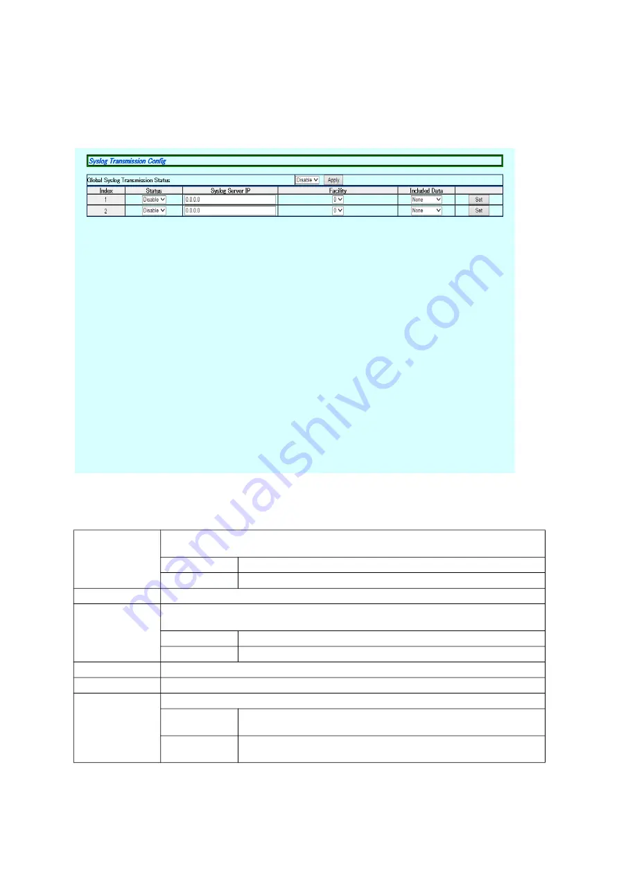
3.1.13. Syslog Transmission Configration

Select  "Basic  Config"  and  "System  Security"  and  then  "Syslog Transmission  Confi

-

gration" to open the screen shown in Figure 3-13. On this screen, you can config

-

ure the settings of the Syslog server to which a system log is sent.

Figure 3-13 Syslog Transmission Configration

Screen Description

Global Syslog 
Transmission 
Status

Displays the settings for sending system logs to the Syslog server.
"Disable" is the factory default setting.
Enable

Sends system logs to the Syslog server.

Disable

Does not send system logs to the Syslog server.

Index

This is the entry number for the Syslog transmission configuration.

Status

Displays the status of each entry.
"Disable" is the factory default setting.
Enable

Setting of the entry is enabled.

Disable

Setting of the entry is disabled.

Syslog Server IP

Displays the IP address of the Syslog server.

Facility

Displays the Facility value.

Included data

Displays information to be added.
SysName

Adds the SysName of this switch to the system log to be trans

-

mitted.

IP address

Adds the IP address of this switch to the system log to be trans

-

mitted.

Summary of Contents for PN28080i-TH

Page 1: ...l for Web Interface Thank you for purchasing our product This manual provides important information about safe and proper operations of this switch Please read Important Safety Instructions on pages 3 to 4 before use For target model names and numbers refer to the next page ...

Page 2: ...l number Firmware version Switch M8eGi PN28080i ID PN28080i TH PN28080i MY PN28080i SG PN28080i NZ 3 0 0 00 or later Switch M16eGi PN28160i ID PN28160i TH PN28160i MY PN28160i SG 3 0 0 00 or later Switch M24eGi PN28240i ID PN28240i TH PN28240i MY PN28240 SG 3 0 0 00 or later ...

Page 3: ...lead to fire electric shock and or equipment failure Do not handle the power cord with wet hand Deviation could lead to electric shock and or equipment failure Do not handle this Switching Hub and connection cables during a thun derstorm Deviation could lead to electric shock Do not disassemble and or modify this Switching Hub Deviation could lead to fire electric shock and or equipment failure Do...

Page 4: ...ing Hub at the location with continuous vibra tion or strong shock or at the unstable location Deviation could lead to injury and or equipment failure Do not install any module other than the separately sold SFP module PN54022 PN54024 to SFP extension slot Deviation could lead to fire electric shock and or equipment failure Do not put this Switching Hub into fire Deviation could lead to explosion ...

Page 5: ...to the power port Deviation could lead to electric fire shock and or malfunction Unplug the power cord if the STATUS ECO LED Status ECO mode blinks in orange system fault Deviation such as keeping connected for a long time could lead to fire When this Switching Hub is installed on wall surface mount it firmly so as not to drop down because of weight of the main body and connec tion cable Deviation...

Page 6: ...ce charged objects in the proximity of them Static electricity could lead to equipment failure Do not put the modular plug of the connected twisted pair cable on objects that can carry static charge such as carpet Do not place it in the proximity Static electricity could lead to equipment failure Do not put a strong shock including dropping to this Switching Hub Deviation could lead to equipment f...

Page 7: ... their respective holders Failure to meet the above conditions may result in fire electric shock break down and or malfunction Please take notice because such cases are out of guarantee Additionally do not cover the bent hole of this Switching Hub Deviation could lead to high internal temperature equipment failure and or malfunction When stacking Switching Hubs leave a minimum of 20 mm space betwe...

Page 8: ...p Configuration 26 3 1 9 Basic Port Config 28 3 1 10 Extend Port Config 30 3 1 11 Power Saving Port Configration 32 3 1 12 System Security 34 3 1 13 Syslog Transmission Configration 36 3 1 14 RADIUS Configuration 37 3 1 15 Telnet Access Limit 38 3 1 16 ID Password Change 39 3 1 17 MAC Learning 40 3 1 18 Static FDB Table 41 3 1 19 FDB Table 42 3 1 20 Time Configration 43 3 1 21 Static ARP Table 44 ...

Page 9: ...6 Loop History Info 69 3 2 17 Port Group Config 70 3 2 18 DMI DDM Config 72 3 2 19 Static Multicat Address 73 3 3 System Tools 74 3 3 1 Software Update 74 3 3 2 Reboot 76 3 3 3 Save Current Config 78 3 3 4 Statistics 79 3 3 5 System log 82 3 3 6 Config File Transfer 84 3 3 7 Ping Execution 86 3 3 8 Exception Handler 88 3 3 9 Watch Dog Timer 89 Appendix A Specifications 90 Appendix B Easy IP Addres...

Page 10: ...10 1 Product Outline Thank you for purchasing Switch M8eGi M16eGi M24eGi hereinafter referred to as this switch This manual provides information required to use the Web control function of this switch ...

Page 11: ...figure the IP address of this switch Select Basic Switch Configuration System IP Configuration Set IP Address to configure the IP address Then select Set Subnet Mask to config ure the subnet mask If required select Set Default Gateway to configure the default gateway address 2 Enabling the Web Control Function Enable the Web control function of this switch From the main menu select Basic Switch Co...

Page 12: ... If the login screen is not displayed check the following 1 Are the IP address subnet mask and default gateway of this switch properly configured 2 Is the IP address of this switch entered on the Web browser 3 Is the Web control function enabled 4 Is the IP address of the terminal to be accessed equal to the network address of this switch When the above information has been authenticated properly ...

Page 13: ...13 Figure 2 2 Select Screen for Display Language Select a language and the screen shown in Figure 2 3 will appear ...

Page 14: ...14 Figure 2 3 Main Screen ...

Page 15: ...nfig Configure the basic settings such as IP address and port settings 3 Advanced Config Configure the advanced settings such as VLAN QoS and IGMP snooping 4 System Tools Use these management tools to update the firmware and browse system logs To conduct operation management it is recommended to conduct the Basic Con fig first before configuring other advanced settings ...

Page 16: ...16 2 3 Displaying Basic Information Selecting General Info opens the screen shown in Figure 2 4 This screen shows a list of basic information of this switch Figure 2 4 General Info ...

Page 17: ...fault setting is blank For configuration details refer to Section 3 1 1 Contact Displays the contact information The factory default setting is blank For configuration details refer to Section 3 1 1 System Address Configure the items shown here in accordance with IP Config in Section 3 1 2 MAC Address Displays the MAC address of this switch This value is uniquely assigned to each device and cannot...

Page 18: ...o open the screen shown in Fig ure 3 1 Select this screen to display this switch s information On this screen you can configure the administrative information such as device name Figure 3 1 Administration Configration Screen Description Products Name Displays the system information This item is not editable Host Name Displays the system name The factory default setting is blank Location Displays t...

Page 19: ...is the factory default setting Default Gateway Displays the IP address of the router set as a current default gateway 0 0 0 0 is the factory default setting IPv6 Status Displays whether access via IPv6 is enabled or disabled Enable Enables access via IPv6 Disable Disables access via IPv6 Factory default setting IPv6 Link Local Address Displays the current IPv6 link local address is the factory def...

Page 20: ... via Telnet or SSH Be sure to configure them If you are unsure consult the network administrator All IP addresses on the local network must be unique and no duplications are allowed In addition you need to set the subnet mask and the default gate way which are the same for other devices on the same subnet using this switch ...

Page 21: ...e entry number on the SNMP manager List Status Displays the SNMP manager status Enable The SNMP manager is enabled Disable The SNMP manager is disabled Privilege Displays the access privilege of the SNMP manager Read Write Both the read and write operations are allowed Read Only Only the read operation is allowed IP Address This is the IP address for an SNMP manager Community This is the community...

Page 22: ...User Name Displays the name of the SNMP user Group Name Displays the name of the SNMP group Authentication Displays the authentication method The following options are used none MD5 and SHA Authentication Key Sets an authentication key Specify Password or Key and enter a password or key Privilege Displays the encryption system The options none and DES are used Privilege Key Sets a privilege key Sp...

Page 23: ...the SNMP manager settings Figure 3 5 SNMP Extend View Config Screen Description Total Entry Displays the number of created SNMP view entries No This is the entry number of the SNMP view View Name Displays the name of the SNMP view Subtree Displays the subtree of the SNMP view View Type Displays the type of the SNMP view The options Included and Excluded are used ...

Page 24: ...oup entries No This is the entry number of the SNMP group Group Name Displays the name of the SNMP group SNMP Version Displays the version of the SNMP group The following options are used v1 v2c and v3 READ_VIEW Displays the name of the view to be read WRITE_VIEW Displays the name of the view to be written NOTIFY_VIEW Displays the name of the view to be notified Security Level Displays the securit...

Page 25: ...the entry number for the trap receiver Status Displays the trap sending setting Enable Sends traps Disable Does not send traps Factory default setting Type Displays the type of traps v1 Sends traps of SNMP v1 Factory default setting v2c Sends traps of SNMP v2c v2 Sends traps of SNMP v3 IP Address This is the IP address for the trap receiver IPv6 Address This is the IPv6 address for the trap receiv...

Page 26: ... Configuration Select Basic Config and SNMP and then Advanced Trap Configuration to open the screen shown in Figure 3 8 On this screen you can configure the operations for sending traps Figure 3 8 Advanced Trap Configuration ...

Page 27: ...t port that has been configured Enable Link UP Configures a port to which the trap is sent Temperature Trap Displays whether the trap sending is enabled or disabled at an abnormal sys tem temperature Enable Enables the trap sending Disable Disables the trap sending Factory default setting Temperature Displays the threshold temperature value to send the trap Fan Failure Displays whether the trap se...

Page 28: ...Select Basic Config and Port Config and then Basic Port Configuration to open the screen shown in Figure 3 9 On this screen you can configure port status dis play settings and mode and other settings Figure 3 9 Basic Port Config ...

Page 29: ... port is available Disable The port is not available Link Status Displays the current link status Up A link has been established successfully Down A link has not been established Duplex Mode Displays the communication speed and full duplex half duplex settings For all ports Auto is the factory default setting Auto Auto negotiation mode 100M Full 100 Mbps full duplex 100M Half 100 Mbps half duplex ...

Page 30: ... Description Global Jumbo Sta tus Displays the jumbo frame settings Enable The jumbo frame is enabled Disable The jumbo frame is disabled Factory default setting Port Number Displays the port number Type Displays the port type 1000T The port type is 1000BASE T 1000X The port type is SFP expansion port Link Status Displays the current link status Up A link has been established successfully Down A l...

Page 31: ...et ting is Disable for all ports Setting this item to Enable forwards EAP frames used in IEEE802 1X authentication Setting this item to Disable destroys EAP frames Enable Indicates that the EAP frame forwarding function is enabled Disable Indicates that the EAP frame forwarding function is disabled ...

Page 32: ... at a time Click the Select All button and all ports will be selected Click the Reset button and all ports will be deselected Click the Set selected port s button after selecting and changing the items for configuring settings at a time and the same settings will apply to the selected ports Port Number Displays the port number Type Displays the port type 1000T The port type is 1000BASE T 1000X The...

Page 33: ... saving mode status is enabled Full Half The MNO series power saving mode status is enabled Half Disable The MNO series power saving mode status is disabled Energy Efficient Displays the EEE Energy Efficient Ethernet status For all ports Enabled is the factory default setting Enabled The EEE is enabled Disabled The EEE is disabled ...

Page 34: ... SSH UI Idle Displays the timeout settings in seconds terminating a SSH connected session if no input is made The factory default setting is 5 minutes Idle Displays the time to want for response to SSH authentication The factory default setting is 120 seconds Retries Time Displays the number of times of retransmission of SSH authentication The factory default setting is 5 SNMP Agent Sta tus Displa...

Page 35: ...CO mode SSH Server Displays the SSH access settings Disable is the factory default setting Enable Access is enabled Disable Access is disabled Login Method 1 2 Displays how to check the username and password for login The factory default setting is Local for 1 and None for 2 Local Login with the username and password set for this switch RADIUS Login with authentication from the RADIUS server None ...

Page 36: ...efault setting Enable Sends system logs to the Syslog server Disable Does not send system logs to the Syslog server Index This is the entry number for the Syslog transmission configuration Status Displays the status of each entry Disable is the factory default setting Enable Setting of the entry is enabled Disable Setting of the entry is disabled Syslog Server IP Displays the IP address of the Sys...

Page 37: ...tory default set ting Server IPv6 Address Displays the IPv6 address of the RADIUS server is the factory default setting Shared Secret Displays the common key Shared Secret that is used in authentication The same key must be set in the server and the client In general the system manager sets this secret key The factory default setting has no secret key Displays encrypted if the key is encrypted Res...

Page 38: ... Telnet access limitation IPv6 Telnet Access Limitation Displays the IPv6 Telnet access limit Disable is the factory default setting Enable Enables the Telnet access limitation Disable Disables the Telnet access limitation Number This is the entry number for the Telnet access limit IP Address Subnet Mask Displays the information on accessible IPv4 networks to be added There is no factory default s...

Page 39: ...assword These settings are required to log in to the console SSH Telnet and Web Current User ID Enter the current username This setting is used to log in to this switch manager is the factory default setting Current Password Enter the current password This setting is used to log in to this switch manager is the factory default setting New User ID Enter a new username New Password Enter a new passw...

Page 40: ...ion Note When IEEE802 1X port based authentication is activated MAC Learning can not be disabled Port Number Displays the port number MAC Learning Displays the MAC Learning statuses of ports Auto is the factory default setting Auto The MAC address is automatically learned and the packet trans mission is executed Disable Auto learning of MAC address is disabled and packet transmis sion is not execu...

Page 41: ... the FDB table Port Select a port to which a MAC address is to be added VLAN ID Select the VLAN ID of a MAC address to be added MAC Address Enter the MAC address to be added Remove Displays the list of manually registered FDB entries Click the Next Page and Previous Page buttons and the display range of the list will be switched Select the entry to be deleted and click the Remove button and it wil...

Page 42: ...ically learned FDB entry is retained It is equal to the time after receiving the last packet The factory default setting is 300 seconds 5 minutes Narrowing down VLAN ID Narrows down records by the specified VLAN ID Narrowing down Port Narrows down records by the specified port number MAC Address Displays the MAC address in the FDB table Port Number Displays the port to which the MAC address has be...

Page 43: ... details ask your network administrator If you wish to disable the time synchronization function set the SNTP server IP to 0 0 0 0 Time Zone Displays the time zone Daylight Saving Displays the application status of Daylight Saving Summer time In case the set time zone is a zone where Daylight Saving is not applied N A is displayed and this configuration is not available When this switch is used do...

Page 44: ... specified in the following items will be registered with the ARP table IP Address Enter the IP address to be added MAC Address Enter the MAC address to be added Remove Displays the list of the manually registered ARP entries Click the Next Page and Previous Page buttons and the display range of the list will be switched Select the entry to be deleted and click the Remove button and it will be rem...

Page 45: ... setting is 7200 seconds 2 hours Order by Sorts the list in a specified order IP Address Sorts the list by IP address MAC Address Sorts the list by MAC address Type Sorts the list by type IP Address Displays the IP address entries on the ARP table MAC Address Displays the MAC address entries on the ARP table Type Displays the type of the registered ARP entry Static Indicates that the ARP entry has...

Page 46: ...e time NDP Stale Time Displays the timeout value of a stale time Total Entry Displays the number of created NDP table entries IPv6 Address Displays the IPv6 address on the NDP table Hardware Address Displays the hardware address on the NDP table Status Displays the status of an adjacent cache Type Displays the type on the NDP table Static Indicates that the ARP entry has been set manually Dynamic ...

Page 47: ...etting VLAN Total Count Displays the switch s current number of VLANs Click the Remove button of each entry and the setting of that VLAN will be removed VLAN ID Displays the VLAN ID of a VLAN VLAN Name Displays the VLAN name VLAN Type Displays the VLAN type Permanent This is the initial setting VLAN This VLAN cannot be removed Static This is a newly provided VLAN Management VLAN Displays whether o...

Page 48: ...nformation Figure 3 25 VLAN Modification Screen Description VLAN ID Displays the VLAN ID VLAN Name Displays the VLAN name Tagged Port Indicates that no tag is used for the frame transmitted from that port Member Port Select whether to assign each port to that VLAN Not Member Port Click the Reset button and the assignment of each port will return to the current status ...

Page 49: ...re 3 26 On this screen you can create a new VLAN Figure 3 26 VLAN Creation Screen Description VLAN ID Set the VLAN ID VLAN Name Set the VLAN name Member Port Select whether to assign each port to that VLAN Not Member Port Click the Reset button and the assignment of each port will return to the cur rent status ...

Page 50: ...rt s button after selecting and changing the items for configuring settings at a time and the same settings will apply to the selected ports Port Number Displays the port number PVID Displays the port s current PVID Port VLAN ID The PVID displays the VLAN ID to which an untagged frame should be transferred when it was received The fac tory default setting is 1 If a tagged frame is received the tag...

Page 51: ...an configure the QoS and Traffic Class settings Figure 3 28 QoS Config Screen Description QoS Displays the setting of the QoS function using IEEE802 1p Disable is the factory default setting Enable QoS is enabled Disable QoS is disabled Priority Displays the priority value in the VLAN tag Traffic Class Displays the priority with which a frame is transferred ...

Page 52: ...ct All button and all ports will be selected Click the Reset button and all ports will be deselected Click the Set selected port s button after selecting and changing the items for configuring settings at a time and the same settings will apply to the selected ports Port Number Displays the port number Bandwidth Displays the bandwidth The factory default setting is 1000 The unit is Mbps Status Dis...

Page 53: ...een shown in Figure 3 30 On this screen you can configure the group settings of link aggre gation Figure 3 30 Link Aggregation Config Screen Description Group Member Select the ports being group members of link aggregation Member Port List Displays the ports included in the group of link aggregation ...

Page 54: ...egation Config and then click the Mod ify button of a group to open the screen shown in Figure 3 31 On the screen you can modify a registered group Figure 3 31 Link Aggregation Modification Screen Description Group Member Select the ports being group members of link aggregation ...

Page 55: ...nging the items for configuring settings at a time and the same settings will apply to the selected ports Port Number Displays the port number Unknown Unicast Enables or disables the Unknown unicast storm control Enable The Unknown unicast storm control is enabled Disable The Unknown unicast storm control is disabled Factory default setting Broadcast Enables or disables the broadcast storm control...

Page 56: ...56 Threshold Displays the threshold value for the number of packets ...

Page 57: ...tus reflects the Port Control setting listed below Unauthorized The authentication is denied Authorized The authentication is approved Port Control Displays the operation for authentication request Auto Enables the authentication function and ignores all the authentication requests from a client Force Unauthorized Disables the authentication function and blocks all com munications Force Authorized...

Page 58: ...t after authentication fails The factory default setting is 60 seconds Re authentication Period This is the interval for periodical re authentication The factory default setting is 3600 seconds Re authentication Status Displays the periodical re authentication setting Enable RADIUS timer The periodical re authentication is performed using the value of the Re authentication timer on the RADIUS serv...

Page 59: ...ys the port number of a port at which packets from other ports can be monitored Monitor Target Displays the port number of a port to be monitored Monitor Direction Displays which of transmit and receive packets are monitored at the port to be monitored Send Recv is the factory default setting Send Monitors transmit packets Recv Monitors receive packets Send Recv Monitors both transmit and receive ...

Page 60: ...60 Note Management packets such as Ping or ARP transmitted from this switch can not be captured ...

Page 61: ...he source IP address Destination IP Address Displays the destination IP address Source IPv6 Address Displays the source IPv6 address Destination IPv6 Address Displays the destination IPv6 address Source MAC Address Displays the source MAC address Destination MAC Address Displays the destination MAC address VLAN ID Displays the VLAN ID 802 1p Priority Displays the IEEE802 1p priority Source Layer 4...

Page 62: ...62 TCP SYN Flag Displays whether or not to use a filter for TCP SYN Flag ICMP Type Displays the ICMP type ...

Page 63: ...ings Figure 3 36 In Profile Action Config Screen Description Total Entry Displays the number of created In profiles number of indexes ID Displays the index number of an In profile Behavior Displays whether to deny or permit packets Deny Denies packets Permit Permits packets Policed DSCP Marks the DSCP value Policed Precedence Marks the precedence value Policed CoS Marks the CoS value ...

Page 64: ...tion Total Entry Displays the number of created Out profiles number of indexes ID Displays the index number of an Out profile Behavior Displays whether to deny or permit packets Deny Denies packets Permit Permits packets C o m m i t t e d Rate Displays the rate at which a packet enters the buffer Burst Size Indicates the burst size of traffic that can be sent exceeding the commit rate The followin...

Page 65: ...k Aggregation function are used simultaneously specify the actual physical port number instead of the number of the logical port created in Link Aggregation Figure 3 38 Port List Config Screen Description Total Entry Displays the number of created port lists number of indexes Port List Index Displays the index number of the port list ID Displays the index number of the port list Port List Displays...

Page 66: ...policies number of indexes ID Displays the index number of the policy Classifier Index Displays the index number of Classifier Policy Sequence Displays the sequence number that indicates the order of application of policies Policies are applied from the one with the smallest sequence number In Profile Action Index Displays the index number of an In profile O u t P r o f i l e Action Index Displays...

Page 67: ... Target Port Select ing Select multiple target ports for configuring settings at a time Click the Select All button and all ports will be selected Click the Reset button and all ports will be deselected Click the Set selected port s button after selecting and changing the items for configuring settings at a time and the same settings will apply to the selected ports Port Number Displays the port n...

Page 68: ... the Loop detection mode for that port Block When the Switching Hub detects loop the ports are blocked Factory default setting Shutdown When the Switching Hub detects loop the ports are shut down Recovery Status Enables disables recovery when a port is blocked Enable Automatically recovers a blocked port after the time specified in Recover Timer passed Factory default setting Disable Does not reco...

Page 69: ...ion Number Displays the loop detection and block event number Time Displays the time when the loop detection and block event occurred Event Displays the description of the loop detection and block event The loop detected on portX Indicates that a loop occurred in switches under the displayed ports The loop detected between portX and portY A loop occurred between the displayed ports PortX auto reco...

Page 70: ...an be assigned to mul tiple port groups Figure 3 42 shows an example of configuration using port group ing Figure 3 42 Example of Configuration Using Port Grouping Configuration to allow communication between PC1 and the Internet and between PC2 PC3 and the Internet Note The Loop detection and blocking function executes loop detection and block ing of frames also between different port groups If t...

Page 71: ... port group ポートグループ メンバーポート Displays the member ports that belong to the port group Total Entry Displays the number of created port groups number of indexes ID Displays a port group ID Name Displays the name of the set port group Member Displays the member ports that belong to the port group Status Displays the status of the port group ...

Page 72: ...ber Port Serial Number Displays the serial number Transceiver Type Displays the Transceiver Type RX Power dBm Displays the current maximum and minimum values of RX Power dBm The maximum and minimum values can be configured TX Power dBm Displays the current maximum and minimum values of TX Power dBm The maximum and minimum values can be configured Temp deg C Displays the current maximum and minimum...

Page 73: ...n Figure 3 45 On this screen you can configure the Static Multicast Group settings Figure 3 45 Static Mulitcast Address Screen Description VLAN ID Displays the VLAN ID of the multicast group Group MAC Address Displays the MAC address of the multicast group Group Member Displays the ports included in a multicast group ...

Page 74: ...the firmware you must save the configuration information in accordance with Section 3 3 3 Unless you save the configuration informa tion the settings configured so far will be deleted upon restart Current Firmaware Version Displays the current firmware version TFTP Server IP Address Displays the IP address of the TFTP server on which the firmware for update has been saved File Name Displays the fi...

Page 75: ... transfer click the Cancel Download but ton Figure 3 47 Firmware Data Being Transferred When it has been completed the firmware data will be rewritten after the screen shown in Figure 3 48 appears Figure 3 48 Firmware Data Being Rewritten When rewriting the data has been completed this switch will be automatically reboot ...

Page 76: ...r reboot is completed Reboot Option Displays the reboot method Normal is the factory default setting Normal Normal reboot is conducted Factory Default All the settings are reset to the factory default settings Factory Default Except IP All the settings except the IP address are reset to the factory default settings Reboot Timer Displays the time between execution of the reboot command and actual r...

Page 77: ...e Reboot button and this switch will be reboot after the screen shown in Figure 3 50 appears Figure 3 50 Rebooting When the switch has been rebooted the Reload button will be enabled Click it to reload the screen ...

Page 78: ...screen you can save configuration information Figure 3 51 Save Current Config Click Save to save the settings of this switch to its internal RAM Unless the config uration information is saved the settings configured so far will not be reflected after restart After saving is completed the message Save Completed is displayed ...

Page 79: ...itch Click the Update button and the elapsed time or counter value will be refreshed Counter Reset Resets each counter value and returns the elapsed time since counter reset to 0 the elapsed time and counter value since power on will not be reset From Counter Reset Switches to the elapsed time and counter value since counter reset From Boot Switches to the elapsed time and counter value since powe...

Page 80: ...th greater than 9216 bytes Fragments Displays the number of error packets that have a packet length less than 64 bytes and have a CRC or alignment error Jabbers Displays the number of error packets that have a packet length less than 1518 bytes and have a CRC or alignment error Collisions Displays the number of packet collisions 64 Byte Pkts Displays the total number of packets having a packet len...

Page 81: ...ure 3 53 Statistic Information of a Counter by Port Screen Description System Uptime Displays the elapsed time since power on of this switch Click the Update button and the elapsed time or counter value will be refreshed Port Number Displays the port number Total Displays the counter value Average sec Displays the average counter value per second ...

Page 82: ... occurred on this switch By viewing events you can keep track of phenomena that occurred on this switch which are useful for network management Figure 3 54 System Log Some of the events displayed on this screen are linked to SNMP traps When trap occurrence has been configured events are displayed The relationship with traps are shown below ...

Page 83: ...umber Time Displays the time when the event occurred Displays the time accumulated after the boot of this switch if the clock is not set Event Displays the description of the event that occurred on this switch Next Page Switches the display range of a list Previous Page Last Page Displays the range of the list including the last event Display Syslog of Number Displays the range of the list includi...

Page 84: ...ion files Figure 3 55 Config File Transfer Screen Description Select Upload to save the configuration information to the TFTP server or Down load to load the configuration information to this switch TFTP Server IP Displays the IP address of the TFTP server that saves and reads configuration infor mation File Name Displays the file name of the configuration information ...

Page 85: ...d has been completed the screen shown in Figure 3 56 will appear Check the execution result Click the Back to previous page and the screen will return to Config File Trans fer Figure 3 56 Execution Result After Completion of Upload ...

Page 86: ...ices connected to this switch Figure 3 57 Ping Execution Screen Description Target IP Address Displays the IP address of the target to which a ping is sent 0 0 0 0 is the factory default setting Number of Request Displays the number of times a ping is to be sent The factory default setting is 10 Timeout Value Displays the timeout time The factory default setting is 3 seconds ...

Page 87: ... Click the Execution button and pings will be sent After the pings have been sent a specified number of times the execution result will appear as shown in Figure 3 58 Figure 3 58 Execution Result of Pings ...

Page 88: ...Screen Description Exception Handler Displays the exception handling function status Enable Enables the exception handling function Disable Disables the exception handling function Factory default setting Exception Handler Mode Displays the exception handling method Debug Message Outputs a debug message to the console when exception handling is detected Factory default setting Reboot Automatically...

Page 89: ...tors that software running on the system works properly When this function is enabled this switch will be reboot if the software has abnormality Figure 3 60 Watchdog Timer Screen Description Watchdog Timer Displays the status of the Watchdog Timer function Enable Enables the Watchdog Timer Disable Disables the Watchdog Timer Factory default setting ...

Page 90: ...90 Refer to Operation Manual for Menu Screens for your switching hub to read the specifications Appendix A Specifications ...

Page 91: ...nfig In the software the item is displayed as Camera name Restrictions The time for accepting setting changes is limited to 20 minutes after power on to ensure security However you can change settings regardless of the time limit if the IP address subnet mask default gateway user name and password values are set to fac tory defaults Even after the time limit is reached you can check the current se...

Page 92: ...on which a loop had recovered within 3 days Communications fail Communications with all ports are down or slow Are the communication speed and mode settings correct When a communication mode signal cannot be properly obtained the switch operates in half duplex mode Switch the communication mode of the connection target to half duplex mode Do not fix the communication mode of the connected device t...

Page 93: ... dealer Product name Model number Product serial number an 11 digit number attached on the back of the product Firmware version The number after Ver labeled on the unit package Problem status Please give as concrete information as possible Within the warranty period Repair service will be provided in accordance with the conditions stipulated in the warranty card Please bring your product and warra...

Page 94: ... 2019 2021 Panasonic Life Solutions Networks Co Ltd 2 12 7 Higashi Shimbashi Minato ku Tokyo Japan 105 0021 URL http panasonic co jp ls plsnw P1019 1111 Date of purchase Product name Switch M Model No No PN28 Firmware version Boot Code Runtime Code Serial No 11 alphanumeric characters labeled on the product Shop Sales com pany Tel Customer service contact Tel ...

Reviews: