


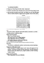


4. Confirm the height of the Audio Control Head is proper. If not,
readjust Black Screws (A) and (B).
7.2.2.3.5. AUDIO CONTROL HEAD HORIZONTAL POSITION ADJUSTMENT
Purpose:
To adjust the Horizontal Position of the Audio Control Head.
Symptom of Misadjustment:
If the Horizontal Position of the Audio Control Head is not
properly adjusted, a maximum envelope cannot be obtained at the
Neutral Position of the Tracking Control Circuit.
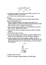
1. Place a jumper between TP6003 and+5V(TP6009) on the TV/VCR
Main C.B.A. to defeat Auto Tracking.
2. Eject the tape and insert it again to access the Neutral Tracking
position.
3. Play back the alignment tape.
4. Connect the oscilloscope to TP3002 on the Video Signal Process
Section of the TV/VCR Main C.B.A. Use TP6205 as a trigger.
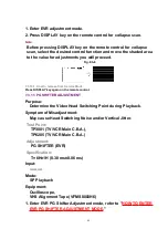
5. Loosen the Black Screw (D) and tighten it slightly. Set the H-
Position Adjustment Driver into the Hole (A). Then slowly turn the
fixture either clockwise or counterclockwise so that the envelope
is at maximum.
Fig. M8
6. Tighten Black Screw (D).
7. Remove the jumper between TP6003 and+5V(TP6009).
55
Summary of Contents for OmniVision PV-C2780-K
Page 8: ...Fig 1 3 Fig 1 4 8 ...
Page 26: ...Fig D5 6 1 2 1 Notes in chart 26 ...
Page 29: ...6 2 2 Inner Parts Location Fig J1 1 29 ...
Page 30: ...6 2 3 EJECT Position Confirmation Fig J1 2 30 ...
Page 31: ...6 2 4 Grounding Plate Unit Full Erase Head and Cylinder Unit Fig J2 1 31 ...
Page 44: ...6 3 CASSETTE UP ASS Y SECTION 6 3 1 Top Plate Wiper Arm Unit and Holder Unit Fig K1 1 44 ...
Page 81: ...81 ...
Page 85: ...11 2 MECHANISM BOTTOM SECTION 85 ...
Page 86: ...11 3 CASSETTE UP COMPARTMENT SECTION 86 ...
Page 87: ...11 4 CHASSIS FRAME SECTION 1 87 ...
Page 88: ...11 5 CHASSIS FRAME SECTION 2 88 ...
Page 89: ...11 6 PACKING PARTS AND ACCESSORIES SECTION 89 ...


