


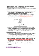


1. Alignment of Main Cam Gear, Drive Rack Arm, and Main Rod
A. Confirm that the hole on Main Rod is a Through Hole with a
hole on chassis.
B. Confirm that the hole on Drive Rack Arm is a Through Hole with
a hole on chassis.
C. Install the Main Cam Gear so that the projection of Main Cam
Gear is in the upward position as shown.
Fig. J3-2
2. Confirmation/Alignment of Intermediate Gear B, Main Cam Gear,
and Intermediate Gear A
A. Confirm that the Hole A on Lift Gear is a Through Hole with a
hole on chassis.
B. Confirm that the hole on Intermediate Gear A is aligned with the
hole on Lift Gear.
Fig. J3-3
C. Install the Intermediate Gear B so that the hole on the
Intermediate Gear B is aligned with the hole on the Main Cam
Gear.
Fig. J3-4
34
Summary of Contents for OmniVision PV-C2780-K
Page 8: ...Fig 1 3 Fig 1 4 8 ...
Page 26: ...Fig D5 6 1 2 1 Notes in chart 26 ...
Page 29: ...6 2 2 Inner Parts Location Fig J1 1 29 ...
Page 30: ...6 2 3 EJECT Position Confirmation Fig J1 2 30 ...
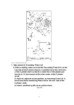
Page 31: ...6 2 4 Grounding Plate Unit Full Erase Head and Cylinder Unit Fig J2 1 31 ...
Page 44: ...6 3 CASSETTE UP ASS Y SECTION 6 3 1 Top Plate Wiper Arm Unit and Holder Unit Fig K1 1 44 ...
Page 81: ...81 ...
Page 85: ...11 2 MECHANISM BOTTOM SECTION 85 ...
Page 86: ...11 3 CASSETTE UP COMPARTMENT SECTION 86 ...
Page 87: ...11 4 CHASSIS FRAME SECTION 1 87 ...
Page 88: ...11 5 CHASSIS FRAME SECTION 2 88 ...
Page 89: ...11 6 PACKING PARTS AND ACCESSORIES SECTION 89 ...


