


5.1.12. HOW TO SET TRACKING TO THE NEUTRAL POSITION
Ejecting the cassette tape and then reinserting it will reset the tracking to the Neutral position.
5.1.13. BLACK SCREWS ON THE CHASSIS
Black Screws are used on the Mechanism Chassis to identify screws that require adjustment.
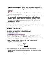
5.1.14. HOW TO RESET ALL COMBINATION VCR MEMORY FUNCTIONS
To reset (clear) the select language, channel auto set and set clock functions to their initial
power on condition (power on, no cassette inserted), hold down the PLAY and FF buttons on
the unit together for more than 5 seconds.
Power will shut off.
5.1.15. HOW TO CONFIRM AUTO CLOCK SET FEATURE
1. Connect an RF cable from the output of one unit to the input of
the test unit.
2. Select corresponding RF channels.
3. Playback a recording of P.B.S. channel including clock set data
and confirm this feature.
5.1.16. VARIABLE VOLTAGE ISOLATION TRANSFORMER
An Isolation Transformer should always be used during the servicing of Combination VCR
whose chassis is not isolated from the AC power line. Use a transformer of adequate power
rating as this protects the technician from accidentsresulting in personal injury from electrical
shocks. It will also protect Combination VCR from being damaged by accidental shorting that
may occur during servicing.
Also, when troubleshooting the above type of Power Supply Circuit, a variable isolation
transformer is required in order to increase the input voltage slowly.
5.1.17. SPECIAL NOTE
All integrated circuits and many other semiconductor devices are electrostatically sensitive and
therefore require the special handling techniques described under the
"ELECTROSTATICALLY SENSITIVE (ES) DEVICES" section of this service manual.
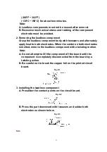
5.1.18. REPLACEMENT PROCEDURE FOR LEADLESS (CHIP) COMPONENTS
The following procedures are recommended for the replacement of the leadless components
used in this unit.
1. Preparation for replacement
A. Soldering Iron
Use a pencil-type soldering iron that uses less than 30 watts.
B. Solder
Eutectic Solder (Tin 63%, Lead 37%) is recommended.
C. Soldering time
Do not apply heat for more than 4 seconds.
D. Preheating
Leadless capacitor must be preheated before installation. -
20
Summary of Contents for OmniVision PV-C2780-K
Page 8: ...Fig 1 3 Fig 1 4 8 ...
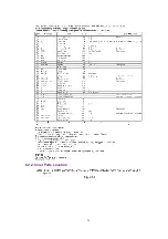
Page 26: ...Fig D5 6 1 2 1 Notes in chart 26 ...
Page 29: ...6 2 2 Inner Parts Location Fig J1 1 29 ...
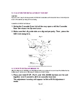
Page 30: ...6 2 3 EJECT Position Confirmation Fig J1 2 30 ...
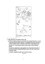
Page 31: ...6 2 4 Grounding Plate Unit Full Erase Head and Cylinder Unit Fig J2 1 31 ...
Page 44: ...6 3 CASSETTE UP ASS Y SECTION 6 3 1 Top Plate Wiper Arm Unit and Holder Unit Fig K1 1 44 ...
Page 81: ...81 ...
Page 85: ...11 2 MECHANISM BOTTOM SECTION 85 ...
Page 86: ...11 3 CASSETTE UP COMPARTMENT SECTION 86 ...
Page 87: ...11 4 CHASSIS FRAME SECTION 1 87 ...
Page 88: ...11 5 CHASSIS FRAME SECTION 2 88 ...
Page 89: ...11 6 PACKING PARTS AND ACCESSORIES SECTION 89 ...


