


2. Perform Step 2 through Step 7 of Method -1.
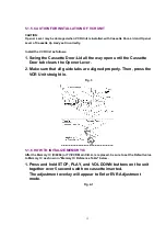
5.1.8.1.3. Method -3:
1. Perform Step 2 through Step 7 of Method -1.
Note:
After repairing mechanical trouble, make sure that all gear
alignments are correct, especially the Wiper Arm Unit and Drive
Rack Unit of Cassette Up Ass'y. (Refer to "
EJECTPosition
Confirmation
" in DISASSEMBLY/ASSEMBLY PROCEDURES.)
5.1.8.2. Electrical Method
Electrical method can only be performed when the mechanism is moved by rotating the Loading
Gear.
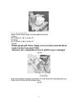
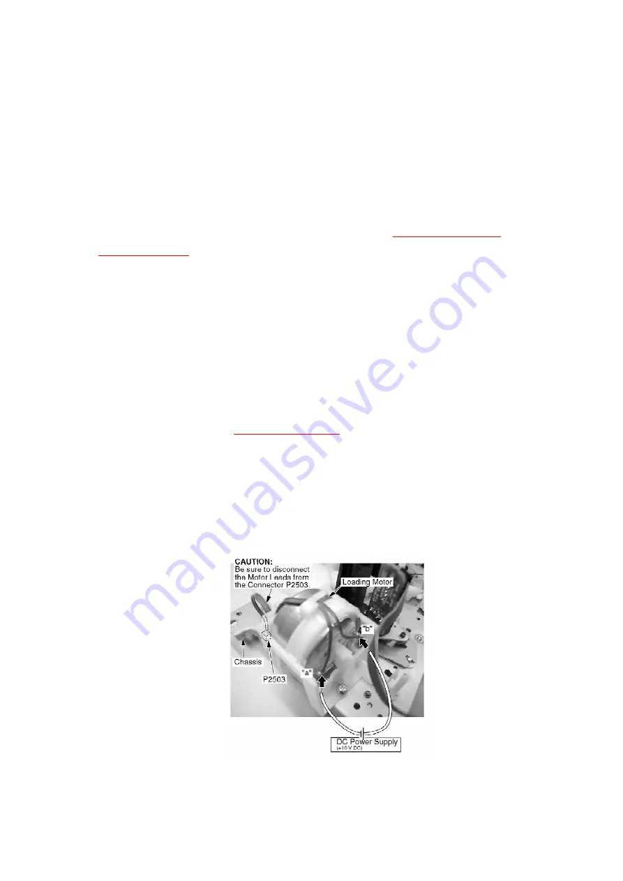
CAUTION:
1. Before applying DC Power Supply, be sure to disconnect the
Motor Leads from the Connector P2503.
Otherwise, the Loading Motor Drive IC (IC2501) may be damaged.
2. If loading does not start in approx. 2 seconds after DC Power
Supply is applied, DO NOT continue to apply DC Power Supply.
Instead, perform "
Manual Method
."
1. Be sure to disconnect the Motor Leads from the Connector P2503.
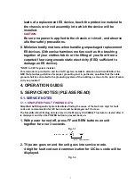
2. Apply+10.0 V DC Power Supply to the Loading Motor terminals.
3. When the Loading Posts reach the fully unloaded position,
remove the Power Supply.
Fig. 7
4. Rewind the tape into the cassette by turning the Center Clutch
18
Summary of Contents for OmniVision PV-C2780-K
Page 8: ...Fig 1 3 Fig 1 4 8 ...
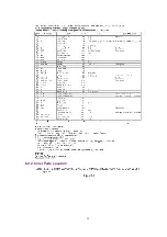
Page 26: ...Fig D5 6 1 2 1 Notes in chart 26 ...
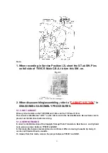
Page 29: ...6 2 2 Inner Parts Location Fig J1 1 29 ...
Page 30: ...6 2 3 EJECT Position Confirmation Fig J1 2 30 ...
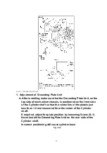
Page 31: ...6 2 4 Grounding Plate Unit Full Erase Head and Cylinder Unit Fig J2 1 31 ...
Page 44: ...6 3 CASSETTE UP ASS Y SECTION 6 3 1 Top Plate Wiper Arm Unit and Holder Unit Fig K1 1 44 ...
Page 81: ...81 ...
Page 85: ...11 2 MECHANISM BOTTOM SECTION 85 ...
Page 86: ...11 3 CASSETTE UP COMPARTMENT SECTION 86 ...
Page 87: ...11 4 CHASSIS FRAME SECTION 1 87 ...
Page 88: ...11 5 CHASSIS FRAME SECTION 2 88 ...
Page 89: ...11 6 PACKING PARTS AND ACCESSORIES SECTION 89 ...


