5.1. CABINET SECTION
5.1.1. Disassembly Flowchart
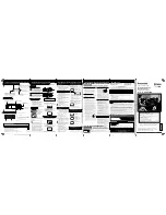
Perform all disassembly procedures in the order described in
the
"Disassembly
Flowchart"
shown
below.
When
reassembling, use the reverse procedure.
CAUTION:
Disconnect AC plug before disassembly.
Fig. D1
5.1.2. Top Cover
5.1.2.1. Disassembly Procedure
1. Remove 2 Screws (A) and 3 Screws (B).
2. Lift up on the rear portion of the Top Cover and remove.
Fig. D2
5.1.2.2. Reassembly Notes
Install the Top Cover front portion at a downward angle so that
the tab on the Front Panel Ass'y fits into the hole in the Top
Cover.
Then, lower the rear portion into place and tighten 2 Screws (A)
and 3 Screws (B).
5.1.3. Bottom Panel
5.1.3.1. Disassembly Procedure
1. Remove 2 Screws with Washers (A), (B), and Screw (C).
2. While pushing 2 Locking Tabs (A) to release, slide the
Bottom Panel and remove.
5 DISASSEMBLY/ASSEMBLY PROCEDURES
19
PV-9661 / PV-9662
Summary of Contents for Omnivision PV-9661
Page 272: ...5 2 MECHANISM SECTION 5 2 1 Disassembly Method Fig J1 1 23 PV 9661 PV 9662...
Page 273: ...5 2 2 EJECT Position Confirmation Fig J1 2 24 PV 9661 PV 9662...
Page 284: ...6 ADJUSTMENT PROCEDURES 6 1 SERVICE FIXTURES AND TOOLS 35 PV 9661 PV 9662...
Page 291: ...6 4 TEST POINTS AND CONTROL LOCATION 42 PV 9661 PV 9662...
Page 311: ...PV 9661 PV 9662 62...
Page 330: ...10 EXPLODED VIEWS 10 1 MECHANISM TOP SECTION 81 PV 9661 PV 9662...
Page 331: ...10 2 MECHANISM BOTTOM SECTION 82 PV 9661 PV 9662...
Page 332: ...10 3 CASSETTE UP COMPARTMENT SECTION 83 PV 9661 PV 9662...
Page 333: ...10 4 CHASSIS FRAME AND CASING PARTS SECTION 84 PV 9661 PV 9662...
Page 334: ...10 5 PACKING PARTS AND ACCESSORIES SECTION 85 PV 9661 PV 9662...