


33
7. SELF- DIAGNOSIS INDICATION DISPLAY
This VTR has a self-diagnosis and display function. If the VTR detects trouble during installation or during use, one of the
following Error Codes will automatically appear in the VTR display. Error Codes are displayed in the form of a single English letter
followed by two numbers, as for example ”H01”.
Note:
1. The indication “U” is displayed on the FIP while power remains on.
2. The indication “H” or “F” is displayed on the FIP, and the power is automatically turned off. When the power is turned on again,
the Error indication code will disappear and the unit will return to normal display mode (either clock or counter is displayed).
3. This Error indication code will be stored in the microprocessor even after the AC plug being disconnected. The two-digit
number portion of the stored Error indication code can be re-displayed in “second” display portion (the last 2 digits of the FIP)
by placing the unit is Service Mode Number 2 When turning on Service Data Display as for example “01” or “02” etc. If a
second error occurs, the most recent error will be displayed and stored until 5 self-diagnosis histories in maximum .
4. To erase the stored Error Code data, Press FF and EJECT buttons on VCR simultaneously for over 5 seconds in Service
Mode 2.
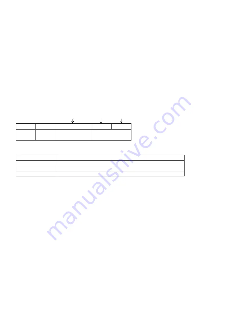
Example of Error Indication on the FIP
F
0
5
HOUR
10min.
1min.
10sec.
1sec.
Blank
Blank
Management Sign
Service Data No.
Division of Management
Management Sign
Management Division
U
User can deal with.
H
Shop can deal with.
F
It should be dealt with in service shop.
Summary of Contents for NV-HV61GN
Page 21: ...2 REMOVAL OF THE BACK PANEL Remove 2 Screws C Remove Screw D Unlock 4 Tabs E Fig D3 21 ...
Page 29: ...10 2 CASING PARTS SECTION 29 ...
Page 30: ...10 3 PACKING PARTS SECTION 30 ...
Page 31: ...11 REPLACEMENT PARTS LIST 31 ...
Page 41: ...C4537 ECJ2VC1H560G CHIP CAPACITOR 41 ...
Page 44: ...D2002 B0AAED000003 DIODE 44 ...
Page 47: ...Q1152 2SC3311ASA TRANSISTOR 47 ...
Page 49: ...R1502 ERJ3GEYJ273V CHIP RESISTOR 49 ...
Page 54: ...W519 ERJ3GEY0R00V CHIP JUMPER 54 ...
Page 109: ...4 1 3 PARTS NAME OF R4 MECHANISM Fig M2 ...
Page 139: ...34 ...