26
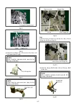
Fig.M3 Connection of Oscilloscope
(2) Playback the Alignment Tape.
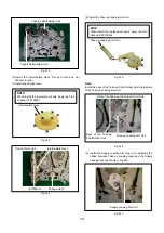
(3) If the RF envelope appears like example ”A” or “B” in Fig.
M4, then adjustment of the tape guide post (P2:
Entrance) is necessary.
(4) Adjust the Tape Guidepost (2) with the post adjustment
screwdriver so that the RF envelope waveform at the
entrance portion becomes flat as shown in Fig.M4”C”.
Fig.M4
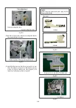
(5) If the envelope appears like “D” or “E” in Fig.M5, then
adjustment of the tape guide post
(P3: Exit) is necessary.
(6) Adjust the tape guidepost (P3) in the same manner as
the P2 post so that the exit portion becomes flat as
shown in Fig.M8”F”.
Fig.M5
(7) Keep pressing the tracking up/down (
∧
or
∨
buttons on
the remote controller unit. The output envelope should
vary nearly parallel with other condition as shown in
Fig.M6.
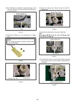
(8) Set the tracking control into center fix position by
pressing the tracking up/down (
∧
or
∨
simultaneously
and adjust for maximum RF envelope, whilst being as flat
as possible.
Fig.M6
Fig.M7
Summary of Contents for NV-HV61GN
Page 21: ...2 REMOVAL OF THE BACK PANEL Remove 2 Screws C Remove Screw D Unlock 4 Tabs E Fig D3 21 ...
Page 29: ...10 2 CASING PARTS SECTION 29 ...
Page 30: ...10 3 PACKING PARTS SECTION 30 ...
Page 31: ...11 REPLACEMENT PARTS LIST 31 ...
Page 41: ...C4537 ECJ2VC1H560G CHIP CAPACITOR 41 ...
Page 44: ...D2002 B0AAED000003 DIODE 44 ...
Page 47: ...Q1152 2SC3311ASA TRANSISTOR 47 ...
Page 49: ...R1502 ERJ3GEYJ273V CHIP RESISTOR 49 ...
Page 54: ...W519 ERJ3GEY0R00V CHIP JUMPER 54 ...
Page 109: ...4 1 3 PARTS NAME OF R4 MECHANISM Fig M2 ...
Page 139: ...34 ...

