111
[Operation Setting]
Operation
Setting
3) Setting of step data
• Do not use the rotary axis operation (Rotary) mode together with the incremental operation (Incremen-
tal) or absolute operation (Absolute).
• If a step data set value specified for the rotary axis operation is out of a range between 0 and [movement per
rotation at a rotary coordinate –1], an error code No. 69 (undefined data error protection) is shown.
4) Jog operation
If you use the motor in the rotary axis operation, do not perform the jog operation after homing completes.
The motor may exceed limitation of the current position. If you perform the jog operation by mistake,
execute the homing again.
5) Servo off
Also if the servo has turned off when the motor is used in the rotary axis operation, the motor may exceed
limitation of the current position. Be sure to execute the homing again after the servo turns on.
Example of Dwell Timer Operation Setting
In the dwell timer operation, the motor operates regarding a set value as waiting time. The dwell time operation is
not used independently. This operation is used as waiting time between the points in the block operation.
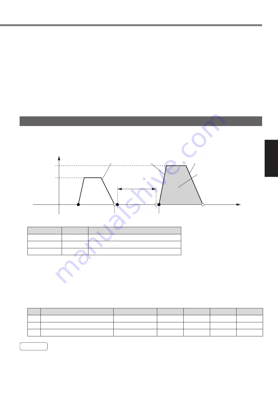
The chart below shows an example to set the point 1 in the dwell timer after the absolute operation at the
point 2 and perform the relative travel at the point 3 after a specified time has passed.
Caution
1) If a waiting time set value (unit: 10 ms) is larger than 214748364, the waiting time is a maximum of
214748364 x 10 ms.
2) To interrupt the dwell timer operation, input emergency stop or deceleration-and-stop signal assigned by
the multi function input (EX-IN1 and EX-IN2: CN X5 Pin 22 and 25).
Speed = VEL2
Speed = VEL1
ACC1
DEC1
Origin = 0
Speed
Time
Waiting time = Point 1 set value
(500 x 10[ms] = 5[s])
End position = X + 1500000
End position = Point 2 set value (+1000000)
Travel = Point 3 set value
(+500000)
Start position = X
DEC2
ACC2
VEL1, VEL2
ACC1, ACC2
DEC1, DEC2
16.Pr**
00, 01
10, 14
12, 16
Parameter name
Positioning setting first speed, second speed
Positioning acceleration setting 1st, 2nd
Positioning deceleration setting 1st, 2nd
• Setting of 16-bit positioning parameter
Dwell timer operation (Dwell time)
Absolute operation (Absolute)
Incremental operation (Incremental)
500
1000000
500000
VEL1
VEL1
VEL2
ACC1
ACC1
ACC2
DEC1
DEC1
DEC2
Single
Single
Single
01
02
03
• Setting of step parameter
1. Set the 16-bit positioning parameter in the table above to any value and specify the step parameter
as shown below.
2. Perform homing. (Refer to “Homing Operation” on page 114.)
3. Specify the point 1 after the point 2 operation has completed and connect the strobe signal input
(STB: CN X5 Pin 24) to COM–. Then, a waiting time operation starts. When a waiting time has
passed, the in-operation signal output (BUSY: CN X5 Pin 28) turns on and the next point 3 operation
can be specified.
Operation mode
Position/Waiting time
Speed
Acceleration Deceleration
Block
No.


