background image

– 13 –

Connecting and Setting up (continued)

COMPONENT VIDEO OUT terminal

These terminals can be used for either interlace or progressive
output and provide a purer picture than the S-VIDEO OUT
terminal.
Connection using these terminals outputs the color difference
signals (P

B

/P

R

) and luminance signal (Y) separately in order to

achieve high fidelity in reproducing colors.
• The description of the component video input terminals

depends on the monitor television (e.g., Y/P

B

/P

R

, Y/B-Y/R-Y,

Y/C

B

/C

R

).

To watch progressive video (NTSC only)

Connect to the component video (480P) input terminals on a
monitor television compatible with this unit's copy guard system.
(Video will not be displayed correctly if connected to an
incompatible monitor television.)
• All Panasonic monitor televisions that have 480P input

terminals are compatible. Consult the manufacturer if you have
another brand of monitor television.

Regarding Progressive Television Picture

Progressive image aspect (height to width ratio) is set at a
standard 16:9. DVD-Video which has been set at 16:9 will be
displayed correctly. However, 4:3 video material will be
stretched to the right and left when displayed.

To view the picture at the right aspect

• For monitor televisions that allow the aspect of progressive

images to be adjusted, use the function provided on the
monitor television and adjust as necessary.

• For monitor televisions which do not allow the aspect of

progressive images to be adjusted, please set “Progressive
(NTSC)” to “Off”.

Note:

• If the unit is connected to the TV through VIDEO OUT or S-

VIDEO OUT, output signal will be interlace only (even if you
select progressive output).

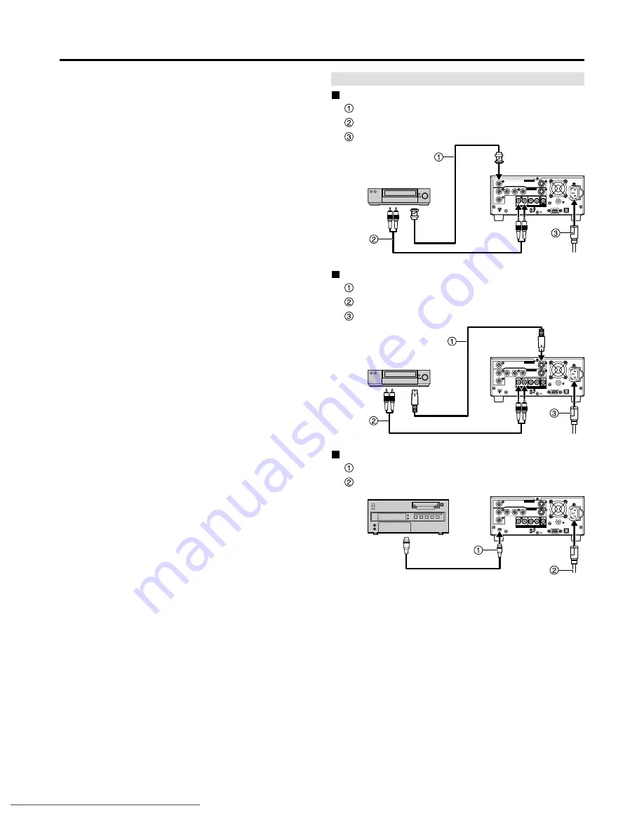
DV terminal

DV cable (4P-4P or 4P-6P)

AC mains lead (supplied)

Notes:

• Be sure to observe the following points when connecting the

IEEE1394 cable (DV cable).

· This unit and all connected equipment should be used with a shared

GND connection. If all equipment is not connected to a shared GND,
turn off the power to all equipment before connecting or removing the
IEEE1394 cable.

· When connecting to equipment having a 6-pin terminal, connect the

IEEE1394 cable to the 6-pin terminal first and then to the terminal on
this unit.

· When connecting to equipment having a 6-pin terminal, be sure to

connect the end of the IEEE1394 cable that matches the terminal
shape. Inserting the wrong end of the plug can damage the unit.

• The DV input on this unit is for use with DV equipment only.
• When DV equipment is connected, it is not possible to operate

the unit from the other equipment.

• Only one piece of DV equipment (e.g., Digital Video Camera)

can be connected to the unit via the DV Input terminal.

• The picture compression system of the DV equipment you have

connected may differ from that used in this unit. In such cases,
dubbing from this equipment will not be possible.

S-Video, stereo audio terminals

S-Video cable (4P)

Stereo Audio cable (PHONO x 2)

AC mains lead (supplied)

Composite video, stereo audio terminals

Video cable (BNC)

Stereo Audio cable (PHONO x 2)

AC mains lead (supplied)

Connecting a video player

VIDEO

VIDEO

S-VIDEO

S-VIDEO

1

2

Y

CH1(A)

DV IN

RS-232C

USB

~ AC IN

PAUSE

REMOTE

CH2(B)

CH1

CH2

PB

PR

VIDEO IN

VIDEO OUT

AUDIO IN

AUDIO OUT

AUDIO

 MON

VIDEO

VIDEO

S-VIDEO

S-VIDEO

1

2

Y

CH1(A)

DV IN

RS-232C

USB

~ AC IN

PAUSE

REMOTE

CH2(B)

CH1

CH2

PB

PR

VIDEO IN

VIDEO OUT

AUDIO IN

AUDIO OUT

AUDIO

 MON

VIDEO

VIDEO

S-VIDEO

S-VIDEO

1

2

Y

CH1(A)

DV IN

RS-232C

USB

~ AC IN

PAUSE

REMOTE

CH2(B)

CH1

CH2

PB

PR

VIDEO IN

VIDEO OUT

AUDIO IN

AUDIO OUT

AUDIO

 MON

DV IN

DV OUT

VIDEO

IN

VIDEO
OUT

S-VIDEO

IN

S-VIDEO
OUT

Video player

Video player

Video player

AUDIO IN

AUDIO

OUT

AUDIO

OUT

AUDIO IN

Downloaded from 

www.Manualslib.com


manuals search engine


Downloaded From Disc-Player.com Panasonic Manuals

Summary of Contents for LQ-MD800P

Page 1: ...MIC CH1 MIN MAX MIN MAX MIN MAX OFF ON CH2 CH2 GB REC INHIBIT DVD VIDEO RECORDER LQ MD800 4 7 Operating Instructions DVD Video Recorder Model No LQ MD800P Model No LQ MD800E Before operating this pro...

Page 2: ...POWER SWITCH IS IN THE OFF POSITION A SMALL CURRENT FLOWS THE FILTER CIRCUIT Operating precaution Operation near any appliance which generates strong magnetic fields may give rise to noise in the vid...

Page 3: ...with Air or with Oxygen or Nitrous Oxide Equipment connected to signal input and or output parts must be certified according to the appropriate IEC 60601 1 and or IEC 60601 1 1 harmonized national st...

Page 4: ...equipment and receiver Connect the equipment into an outlet on a circuit different from that to which the receiver is connected Consult the dealer or an experienced radio TV technician for help The us...

Page 5: ...are coloured in accordance with the following code Green and Yellow Earth Blue Neutral Brown Live As the colours of the wires in the mains lead of this appliance may not correspond with the coloured...

Page 6: ...ng DVD Video 24 Using the SEARCH PROGRAM 25 Selecting programs to play 25 Erasing programs Erase 26 Entering and editing program titles Enter Title 26 Checking program contents Properties 26 Protectin...

Page 7: ...watch see page 25 Use the SEARCH PROGRAM to find a program you have recorded and start play The MENU window shows you most of the features you can use see page 22 The MENU window has most of the featu...

Page 8: ...IFT SEARCH Press to use menu functions Status button STATUS Press to use the status display function Functions button FUNCTION SHIFT STATUS Press to use the function menu Cursor buttons Used to select...

Page 9: ...sed lighting stopped Remain REMAIN provides rough indication of the disc remaining amount Each lamp goes off one after another according to the decrease of the disc remaining amount This is not an exa...

Page 10: ...2 output connector PHONO Analog audio output Audio Monitor output connector PHONO Analog audio output Use the Monitor setting item in the FUNCTION menus to assign the channel to be output RS 232C Remo...

Page 11: ...ut when you start recording after inserting the disc or turning the unit on Recording may become impossible after the disc is optimized more than 50 times Play may be impossible in some cases due to t...

Page 12: ...ive dust Do not block its vents or place where it can become hot First of all please disconnect AC mains leads of all units which you are going to connect with before connecting and disconnecting cabl...

Page 13: ...e following points when connecting the IEEE1394 cable DV cable This unit and all connected equipment should be used with a shared GND connection If all equipment is not connected to a shared GND turn...

Page 14: ...32C USB AC IN PAUSE REMOTE CH2 B CH1 CH2 PB PR VIDEO IN VIDEO OUT AUDIO IN AUDIO OUT AUDIO MON Type B connector Type A connector USB cable USB Notes When a microphone is connected the sound recorded t...

Page 15: ...Zone Second Month Day Year Hour Minute Second Month Day Year Time Zone Clock Settings Clock After performing steps 1 to 3 of TV Screen type perform the following steps 4 Use to select the Picture and...

Page 16: ...isc without cartridge Press to the rear Label up Arrow in Available recording time and recording mode e g 0 50 XP indicates 50 minutes in XP mode Use a disc that can be recorded on and that has enough...

Page 17: ...ard Each press shows the next or previous frame Press PLAY to return to normal Frame by frame viewing You can skip to the beginning of tracks and chapters or markers and restart play from there During...

Page 18: ...ven if you pause play restart play start slow motion or frame by frame Instant repeat is cancelled if you stop play skip items or start recording or search Notes You cannot use instant repeat play whi...

Page 19: ...splay is blanked Available recording time and recording mode e g 0 50 XP indicates 50 minutes in XP mode The current date and time for USA and Canada Hour Minute Second Month Day Year for Europe Hour...

Page 20: ...isc or unit These menus allow you to perform operations by changing this information Soundtrack Soundtrack language Change the number to select a soundtrack Audio attribute LPCM PPCM Digital Signal ty...

Page 21: ...Color Adjust the shade of the picture s color 7 to 7 Page 2 2 of Detail picture adjustment User ENTER Gamma Increases the brightness of the center ranges to improve detail and contrast in dark scenes...

Page 22: ...y disc s menus DVD PLAY LIST Playing Play Lists Play Scenes Edit PL Copy PL Erase Enter Title Properties RAM RAM RAM RAM RAM RAM RAM DISC INFORMATION Enter Title Disc Protection Erase all programs For...

Page 23: ...R or RETURN Notes The disc title will also be erased If protection is active on even one program you cannot erase all programs For your reference You cannot erase computer data Nothing will be erased...

Page 24: ...mpossible You cannot record on DVD R that have been finalized Programs longer than 5 minutes will be divided into about 5 minute chapters The markers you entered will be lost Finalizing takes up to ab...

Page 25: ...ent encoding system from that of the TV system currently selected on the unit Unable to play Displayed if you cannot play the program Currently recording Displayed when the program is being recorded S...

Page 26: ...g time may not increase after erasing short programs Computer data is not erased The available recording time on DVD R does not increase when you erase programs To return to the previous screen Press...

Page 27: ...n point is at an appropriate location Notes The divided programs retain the title of the original program A minute portion of the recording directly preceding the division point may be lost For your r...

Page 28: ...ttom of the play list Play list information This shows the play list number date of creation date month total play time and the number of scenes it contains and title if entered Scenes 9 scenes can be...

Page 29: ...motion while playing scenes just as you can during normal play To stop PLAY LIST play Press The play list appears For your reference Recording mode does not appear on the unit s display while playing...

Page 30: ...o erase and press ENTER 7 Use to select Yes and press ENTER 6 Use to select the scene you want to move and press ENTER 7 Use to select the scene currently in the position to which you want to move the...

Page 31: ...ess 4 Use to select PL Copy and press ENTER 5 Use to select Yes and press ENTER RAM Copying PLAY LIST PL Copy 1 Press MENU SHIFT SEARCH to show the MENU window 2 Use to select the PLAY LIST and press...

Page 32: ...entering the title by using to select SET and pressing ENTER You can Title discs with the DISC INFORMATION in the MENU window Title programs with the SEARCH Title play lists with the PLAY LIST screen...

Page 33: ...ned items are the factory presets Effective items during play Effective items during recording Settings Clock see page 15 You can adjust the clock Repeat Duration Decide the length of the repeated sec...

Page 34: ...nent Video Output Level When connected to a monitor television through the COMPONENT VIDEO OUT Y PB PR terminals Lighter Normal Darker PLAY PLAY REC REC REC Note When the Black Level of the input sign...

Page 35: ...eference Norm 4 3 Wide 16 9 Progressive NTSC On Off On Select when connecting to a NTSC monitor television with component video input terminals Off Select when connecting to a PAL monitor television R...

Page 36: ...ectly exposed to a heat vent or heating appliance The precision parts in this unit are readily affected by the environment especially temperature humidity and dust Observe the following points to ensu...

Page 37: ...ose to the original when played back S Video output The color and luminance signals are separated before being sent to the monitor television making for greater picture clarity Time Zone Time Zone sho...

Page 38: ...ted an incompatible disc The write protect tab on the cartridge is set to PROTECT Use a ballpoint pen or similar to release the write protection The program is write protected Release the protection w...

Page 39: ...t can not be read for the disc which doesn t cope with it Exchange a disc Take the cleaner out of the unit Insert a disc the unit can play Insert a disc the unit can play or record on The unit switche...

Page 40: ...4 Pull the tray out horizontally Emergency ejection can cause damage so it should be avoided if possible To restore the tray turn the unit on and press OPEN CLOSE The tray may close when you turn the...

Page 41: ...pears longer or shorter than it actually is The available recording time doesn t increase even after erasing all recordings on the disc A part or whole of a recorded program has been lost You haven t...

Page 42: ...signals Regarding copyright Pin No 1 2 3 4 5 Signal name N C TXD RXD N C SG Signal name DSR RTS Shorted to 8 CTS Shorted to 7 N C Pin No 6 7 8 9 1 5 6 9 Pin No 1 2 Signal name GND PAUSE STATUS Signal...

Page 43: ...nbalanced MONITOR Out PHONO Reference level 10 dBv 600 unbalanced Headphones Out Stereo mini jack Reference level Maximum 28 dBv variable 8 unbalanced Video Video System NTSC color signal 525 Lines 60...

Page 44: ...ay Secaucus NJ 07094 1 800 880 8474 http www panasonic com medical Panasonic Marketing Europe GmbH Hagenauer Str 43 65203 Wiesbaden Germany 2003 Matsushita Electric Industrial Co Ltd All Rights Reserv...

Reviews: