– 100 –
Chapter 5 Basic Operations — Video memory
2
1
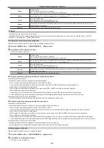
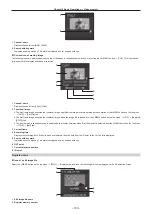
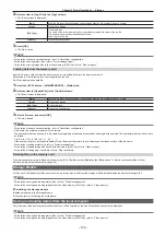
1 Channel name
Displays channels from [Still1], [Still2].
2 Source with key mark
Indicates a source with key. This mark is displayed only for sources with key.
r
Current icon of moving image
The following icons are displayed across the top of the pages in the tabs shown when you select top menu <MEM> button
→
[CLIP]. This icon is used
for playback status display and channel selection.
2
3
4
1
5
6
7
8
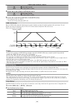
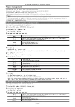
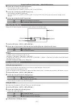
1 Channel name
Displays channels from [Clip1], [Clip2].
2 Thumbnail image
f
The first frame image becomes the thumbnail image right after the image is recorded through the operation of the <MEM> button on the top menu
→
[CLIP]
→
[Rec Clip] tab.
f
The first frame image becomes the thumbnail image when the image file is loaded from the <MEM> button on the top menu
→
[CLIP]
→
[Register]/
[SD/PC] tab.
f
The frame which is currently playing is updated as the thumbnail image when [Get Thumbnail] is selected from the <MEM> button on the top menu
→
[CLIP]
→
[Edit] tab.
3 Current frame
4 Recording time
Displays the recording time. If the clip has been trimmed, then the time from the IN point to the OUT point is displayed.
5 Source with key mark
Indicates a source with key. This mark is displayed only for sources with key.
6 OUT point
7 Current playback position
8 IN point
Register icons
r
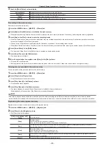
Icon of a still image file
Select the <MEM> button on the top menu
→
[STILL]
→
[Register] tab, and then the following file icon is displayed on the file selection screen.
1
3
2
4
5
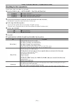
1 Still image file name
2 Register memory number
Summary of Contents for Live Production Suite Series
Page 5: ...Please read this chapter and check the accessories before use Chapter 1 Overview ...
Page 11: ...This chapter describes installation and connection Chapter 2 Installation and Connection ...
Page 50: ...This chapter describes menu operations Chapter 5 Basic Operations ...
Page 113: ...This chapter describes the configuration of operations Chapter 7 Configuring Operations ...
Page 122: ...This chapter describes how to operate system menus Chapter 8 System Menu ...
Page 136: ...This chapter describes plug in functions Chapter 9 External Interfaces ...
Page 140: ... 140 Chapter 10 Specifications Dimensions Dimensions of the XPT Unit AV LSX10 Unit mm inch ...
Page 141: ... 141 Chapter 10 Specifications Dimensions Dimensions of the ME Unit AV LSM10 Unit mm inch ...
Page 153: ...This chapter describes the setting menu table and terms Chapter 11 Appendix ...
Page 176: ...Web Site https www panasonic com Panasonic Corporation 2020 ...

