Panasonic KX-NS8188, Installation Manual
The Panasonic KX-NS8188 is a cutting-edge communication system that revolutionizes office connectivity. Ensure a seamless installation with our comprehensive Installation Manual, available for free download on our website. Get the most out of your device and optimize its performance by accessing the user manual at manualshive.com today.
Share
Download


Reviews:
No comments
Related manuals for KX-NS8188

604002
Brand: cable matters Pages: 12

MC300 Prism
Brand: Quantum Pages: 4

DLT-V4
Brand: Quantum Pages: 2

XBT-PACX
Brand: X-Micro Pages: 6

32-bit PCI Fast Ethernet Network Adapter...
Brand: D-Link Pages: 16

Therma-Cord TC-2000
Brand: Radiant Solutions Pages: 2

Freedom SW 2000
Brand: Xantrex Pages: 36

CrossPower C4L5200-ETH
Brand: C4Line Pages: 26

FB200AS
Brand: Firmtech Pages: 68

NP285
Brand: NetComm Pages: 32

AL-KO M
Brand: Truma Pages: 4
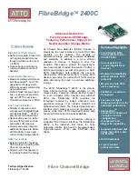
FibreBridge 2400C
Brand: ATTO Technology Pages: 2

AT2112
Brand: Sailor Pages: 25

G-220 V2
Brand: ZyXEL Communications Pages: 95

B-EP800-AC-QM-R
Brand: Toshiba Pages: 3

B-EP802-DC12-QM-R
Brand: Toshiba Pages: 8
Canvio Cast
Brand: Toshiba Pages: 50

4400 Series
Brand: Toshiba Pages: 138


