


18
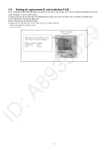
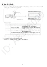
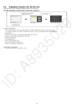
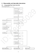
6.4.
Adjustment function for the Service
Touch the [14] of LCD, select the adjustment function for the service.
Operation Specifications (until before the start of the adjustment)
Function description
The service adjustment do setup and adjustment of the following items required in the field service.
For a detailed content, such as the adjustment procedure, refer to “9 Measurements and Adjustments”.
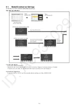
• Model setting
• Setting of the file name for adjustment data backup to SD card.
• Execution of adjustment data backup to SD card
• Checking of Switches
• Camera adjustment
• Zoom Tracking adjustments
• Indoor White Balance Adjustment
• Outdoor White Balance Adjustment
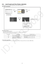
End method of operation
• Press the power button to turn the unit off.
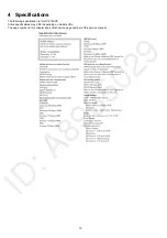
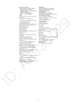
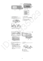
Summary of Contents for HC-V180PP
Page 11: ...11 ...
Page 13: ...13 ...
Page 23: ...23 8 2 PCB Location ...
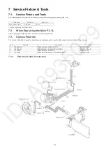
Page 26: ...26 8 3 1 Removal of the Side Case L Unit Fig D1 Fig D2 ...
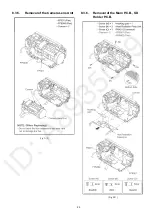
Page 28: ...28 8 3 4 Removal of the Lens Frame Unit Fig D8 Fig D9 ...
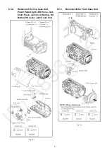
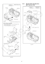
Page 30: ...30 Fig D12 8 3 7 Removal of the Top Operation BATT Catcher P C B Fig D13 ...
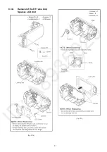
Page 31: ...31 8 3 8 Removal of the R Frame Unit Speaker LCD Unit Fig D14 Fig D15 ...
Page 33: ...33 Fig D18 8 3 10 Removal of the Spring Holder Bar rier Lever Fig D19 ...
Page 35: ...35 8 3 13 Removal of the MOS Unit IR Cut Grass Fig D22 Fig D23 ...
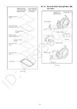
Page 36: ...36 Fig D24 8 3 14 Removal of the 2nd Stepping Motor Fig D25 ...
Page 37: ...37 Fig D26 8 3 15 Removal of the 3rd Stepping Motor Fig D27 ...
Page 38: ...38 Fig D28 8 3 16 Removal of the Focus Motor Fig D29 ...
Page 39: ...39 Fig D30 ...
Page 43: ...43 9 1 2 Adjustment Items Adjustment item as follows ...
Page 46: ...46 ...
Page 47: ...47 ...
Page 48: ...48 ...
Page 49: ...49 ...
Page 50: ...50 ...
Page 51: ...51 ...


