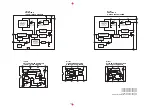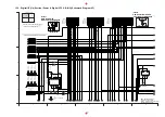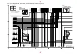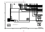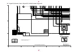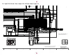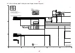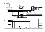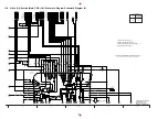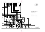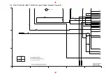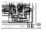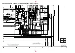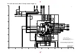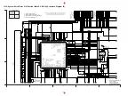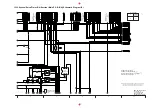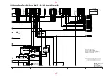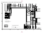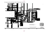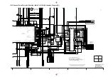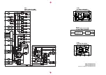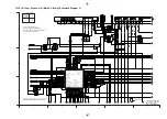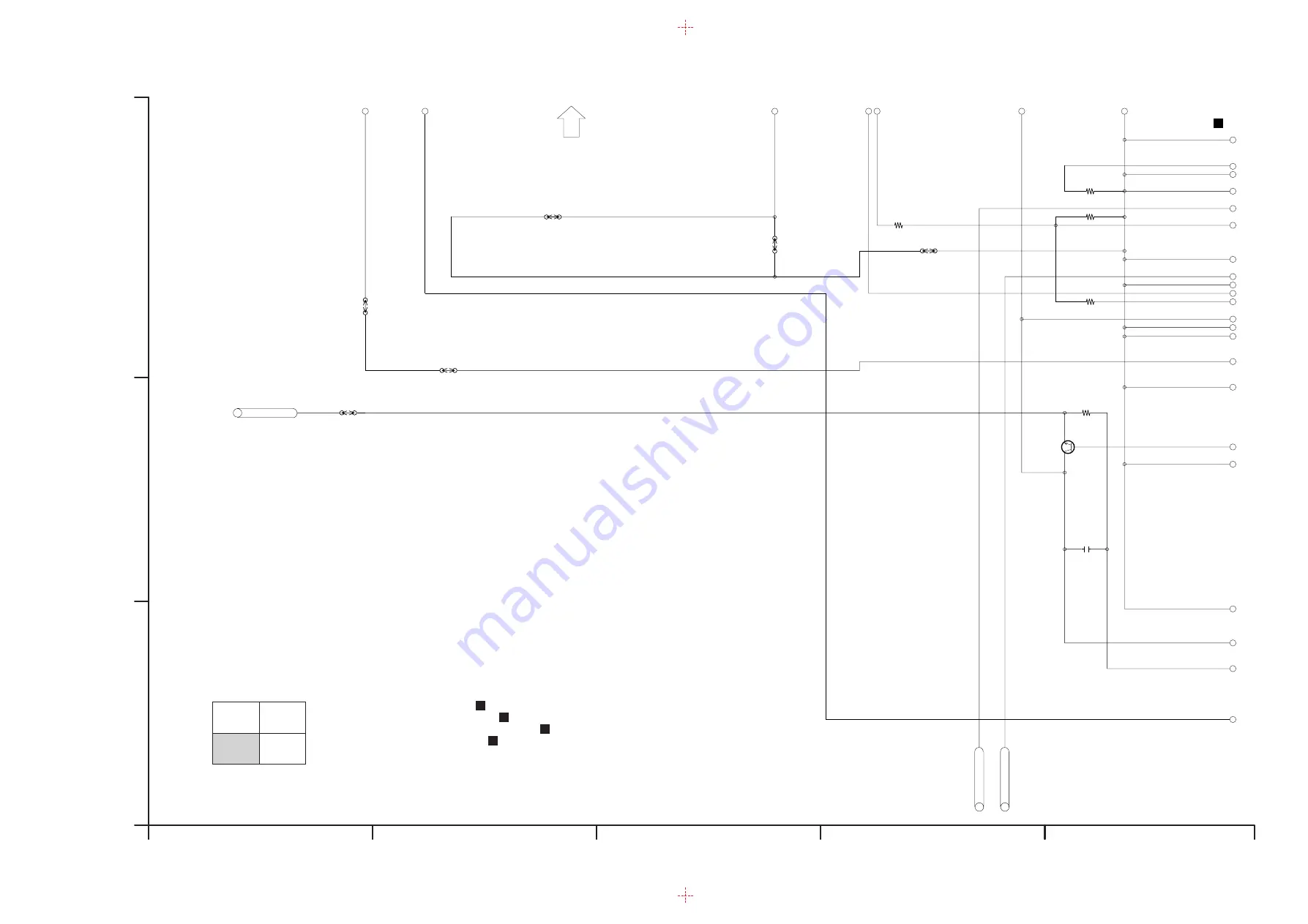
13.9. Video (3/4) Section (Main P.C.B.(1/4)) Schematic Diagram Schematic Diagram (V)
R3021
2200
R3022
3300
R3032
3900
K3003
VWJ0795=7.5
K3033
VWJ0795=12.5
1500
R3023
K3011
VWJ0795=15
VWJ0795=12.5
K3005
OSD_VIDEO_IN
K3034
VWJ0795=12.5
K3004
0
TUN_V_IN1
MIX_V_OUT
2SD1819A0L
Q3004
C3053
0.1[KB]
330
R3031
S
I
I
II
A
B
C
D
E
F
G
1
2
3
4
5
6
7
8
9
10
11
12
13
14
15
16
17
18
19
20
21
22
5
4
3
2
1
C
B
A
C
TO
VIDEO SECTION
(1/4)
NOTE:DO NOT USE THE PART NUMBER SHOWN ON THIS DRAWING FOR ORDERRING.
THE CORRECT PART NUMBER IS SHOWN IN THE PARTS LIST,AND MAY BE
SLIGHTLYDIFFERNT OR AMENDED SINCE THIS DRAWING WAS PREPARED.
LOCATION MAP
1/4
2/4
3/4
4/4
DMR-ES45VP/ES46VP
Video(3/4) Section
(Main P.C.B.(1/4))
Schematic Diagram(V)
V:Video Section:(Page: )
C
A:VHS Audio Section:(Page: )
D
S:Syscon/Servo/Timer Section:(Page: )
I:I/O Tuner Section:(Page: )
E
F
67
Summary of Contents for DMR-ES45VP
Page 7: ...3 Service Navigation 3 1 Service Information 4 Specifications 7 ...
Page 68: ...10 13 Main P C B 1 Disconnect 5 Connectors 2 Remove 2 Screws A and remove Main P C B 52 ...
Page 70: ...11 1 2 Checking and Repairing of Main P C B 54 ...
Page 71: ...11 1 3 Checking and Repairing of RAM Digital P C B Module 55 ...
Page 73: ...11 2 3 Items that should be done after replacing parts 57 ...
Page 74: ...58 ...
Page 75: ......
Page 87: ...17 1 2 Casing Parts Mechanism Section 2 70 ...
Page 88: ...17 1 3 VHS Mechanism Section 71 ...
Page 89: ...17 1 4 Packing Accessories Section 72 ...
Page 111: ...C11701 F2A1A2220055 10V 2200U 1 94 ...
Page 123: ......
Page 124: ......
Page 132: ...1 4 2 4 3 4 4 4 DMR ES45VP ES46VP Main P C B VEPV0054BT 4 4 Section Location Map REAR FRONT ...

