48
10 Measurements and Adjustments
10.1. Introduction
When servicing this unit, make sure to perform the adjustments necessary based on the part(s) replaced.
Before disassembling the unit, it is recommended to back up the camera data stored in flash-rom as a data file.
NOTICE (When Main P.C.B. is exchanged)
Number of necessary adjustment items decreases by copying the backup data to new Main P.C.B. when adjustment data in old
Main P.C.B. can be read by ROM_BACKUP "DSC
→
SD" in "10.2.2. Flash-Rom Data Backup".
For more details, please refer an item "MAIN PCB (to which the backup data was copied)" in the table of "10.3.2. Adjustment
Specifications".
IMPORTANT NOTICE (After replacing the Main P.C.B.)
After replacing the Main P.C.B., it is necessary to achieve adjustment.
10.2. Before Disassembling the unit
10.2.1.
Initial Setting Release
The cameras specification are initially set in accordance with model suffix (such as EB, EG, GC, and so on.).
Unless the initial setting is not released, an automatic alignment software in the camera is not able to be executed when the
alignment is carried out.
Note:
The initial setting should be again done after completing the alignment. Otherwise, the camera may not work properly.
Therefore as a warning, the camera display a warning symbol " ! " on the LCD monitor every time the camera is turned off.
Refer to the procedure described in "3.5.2. INITIAL SETTINGS" for details.
[How to Release the camera initial setting]
Preparation:
Attach the Battery to the unit.
Set to P(Program AE) mode by operating the mode button.
Step 1. Temporary cancellation of "INITIAL SETTINGS":
While pressing the UP of Cursor button and MOTION PICTURE button simultaneously, turn the Power on.
Step 2. Cancellation of "INITIAL SETTINGS":
Press the PLAYBACK switch.
While pressing UP of Cursor button and MOTION PICTURE button simultaneously, turn the Power off. (The warning symbol " ! " is
displayed on the LCD monitor.)
Summary of Contents for DMC-FT5EA
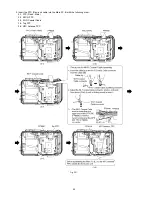
Page 36: ...36 9 Disassembly and Assembly Instructions 9 1 Disassembly Flow Chart 9 2 P C B Location ...
Page 38: ...38 9 3 2 Removal of Rear Aluminum Case Unit Fig D2 9 3 3 Removal of Rear Case Unit Fig D3 ...
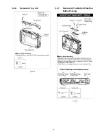
Page 44: ...44 9 3 8 Removal of Top FPC Unit Fig D14 9 3 9 Removal of Speaker Fig D15 ...
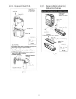
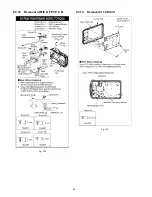
Page 46: ...46 9 3 12 Removal of MIC G FPC P C B Fig D18 9 3 13 Removal of LCD Unit Fig D19 ...
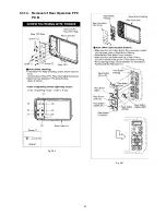
Page 47: ...47 9 3 14 Removal of Rear Operation FPC P C B Fig D20 Fig D21 ...
Page 56: ...56 ...

