35
8.2.
When Replacing the Main P.C.B.
After replacing the Main P.C.B., be sure to achieve adjustment.
8.3.
Service Position
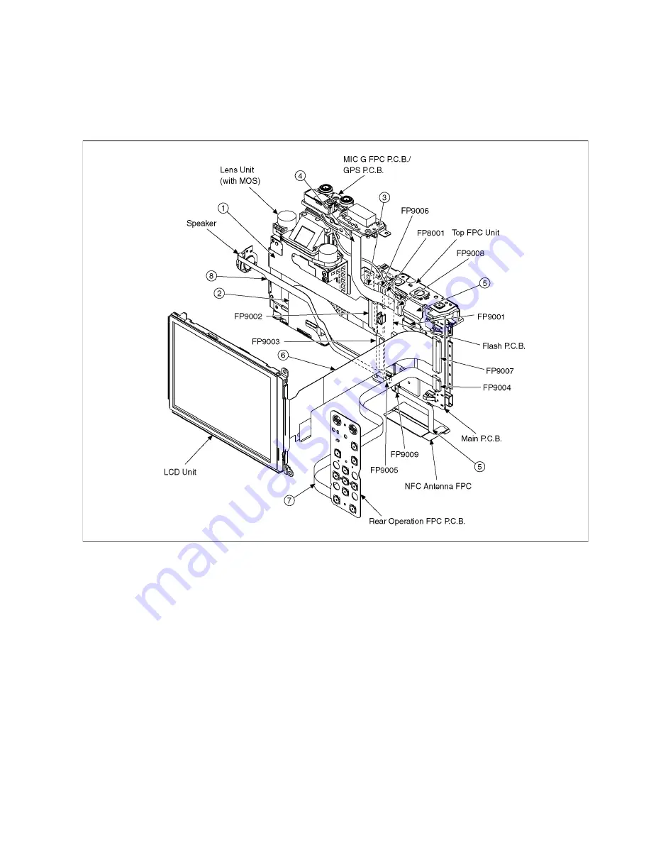
This Service Position is used for checking and replacing parts. Use the original cables for servicing.
8.3.1.
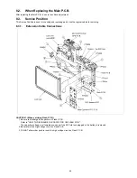
Extension Cable Connections
CAUTION-1. (When servicing Flash P.C.B.)
1. Be sure to discharge the capacitor on Flash P.C.B.
Refer to "HOW TO DISCHARGE THE CAPACITOR ON FLASH P.C.B.".
The capacitor voltage is not lowered soon even if the AC Cord is unplugged or the battery is removed.
2. Be careful of the high voltage circuit on Flash P.C.B.
3. DO NOT allow other parts to touch the high voltage circuit on Flash P.C.B.
Summary of Contents for DMC-FT5EA
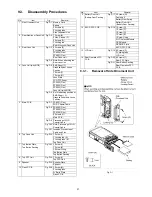
Page 36: ...36 9 Disassembly and Assembly Instructions 9 1 Disassembly Flow Chart 9 2 P C B Location ...
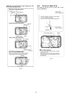
Page 38: ...38 9 3 2 Removal of Rear Aluminum Case Unit Fig D2 9 3 3 Removal of Rear Case Unit Fig D3 ...
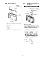
Page 44: ...44 9 3 8 Removal of Top FPC Unit Fig D14 9 3 9 Removal of Speaker Fig D15 ...
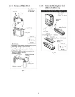
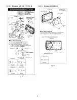
Page 46: ...46 9 3 12 Removal of MIC G FPC P C B Fig D18 9 3 13 Removal of LCD Unit Fig D19 ...
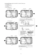
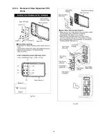
Page 47: ...47 9 3 14 Removal of Rear Operation FPC P C B Fig D20 Fig D21 ...
Page 56: ...56 ...

