36
Note when repairing PCB
In this unit, battery door lock detection switch is mounted on Main PCB so as to secure the waterproof performance.
Be careful of following points.
(1)Before removing Main PCB, be sure to cancel Initial setting.
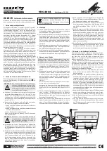
If the unit is turned on while Battery Door is not locked correctly, the following warning display as right figure appears on LCD,
and
this unit cannot be operated.
When Main PCB was removed, this battery door lock detection switch becomes to status of "Battery Door: OPEN".
Thus battery door lock detection switch does not operate correctly.
And even if the unit is turned on, this unit cannot be operated.
When initial setting was cancelled, battery door lock detection switch is ignored and the unit always be in status of
"Battery Door: CLOSE" and the unit can be operated even if Main PCB is removed.
CAUTION-1. (When servicing FLASH PCB)
1. Be sure to discharge the capacitor on FLASH PCB.
Refer to “HOW TO DISCHARGE THE CAPACITOR ON FLASH PCB”.
The capacitor voltage is not lowered soon even if the AC Cord is unplugged or the battery is removed.
2. Be careful of the high voltage circuit on FLASH PCB.
3. DO NOT allow other parts to touch the high voltage circuit on FLASH PCB.
Summary of Contents for DMC-FT1EB
Page 15: ...15 4 Specifications ...
Page 16: ...16 ...
Page 18: ...18 ...
Page 19: ...19 ...
Page 20: ...20 ...
Page 21: ...21 5 Location of Controls and Components ...
Page 22: ...22 ...
Page 31: ...31 7 2 Air leak Test ...
Page 32: ...32 7 3 Air leak Test Inspection ...
Page 33: ...33 ...
Page 37: ...37 9 Disassembly and Assembly Instructions 9 1 Disassembly Flow Chart 9 2 PCB Location ...
Page 39: ...39 9 3 2 Removal of Top Ornament Fig D2 Fig D3 ...
Page 40: ...40 9 3 3 Removal of Rear Case Unit Fig D4 Fig D5 ...
Page 42: ...42 Fig D7 9 3 5 Removal of Main P C B Battery Case Fig D8 ...
Page 43: ...43 Fig D9 9 3 6 Removal of Main P C B Fig D10 ...
Page 44: ...44 Fig D11 9 3 7 Removal of Flash P C B Fig D12 ...
Page 45: ...45 9 3 8 Removal of Top P C B Fig D13 Fig D14 ...
Page 46: ...46 9 3 9 Removal of Rear Operation P C B Fig D15 Fig D16 ...
Page 47: ...47 Fig D17 9 3 10 Removal of LCD Unit Fig D18 ...