


88
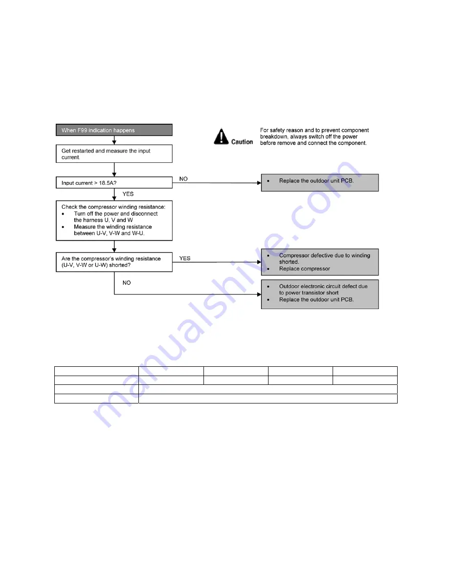
15.4.30 F99 (Output Over Current Detection)
Malfunction Decision Conditions
•
During operation of cooling and heating, when an output over-current (18.5A) is detected by checking the current
that flows in the inverter DC peak sensing circuitry.
Malfunction Caused
•
DC peak due to compressor failure.
•
DC peak due to defective power transistor(s).
•
DC peak due to defective outdoor unit PCB.
Troubleshooting
•
Checking the power transistor
•
Never touch any live parts for at least 10 minutes after turning off the circuit breaker.
•
If unavoidable necessary to touch a live part, make sure the power transistor’s supply voltage is below 50V using
the tester.
•
For the UVW, make measurement at the Faston terminal on the board of the relay connector.
Tester’s negative terminal
Power transistor (+)
UVW
Power transistor (-)
UVW
Tester’s positive terminal
UVW
Power transistor (+)
UVW
Power transistor (-)
Normal resistance
Several k
Ω
to several M
Ω
Abnormal resistance
0 or
∞
Summary of Contents for CS-NE9NKE
Page 12: ...12 4 Location of Controls and Components 4 1 Indoor Unit 4 2 Outdoor Unit 4 3 Remote Control...
Page 13: ...13 5 Dimensions 5 1 Indoor Unit...
Page 14: ...14 5 2 Outdoor Unit...
Page 15: ...15 6 Refrigeration Cycle Diagram...
Page 16: ...16 7 Block Diagram...
Page 17: ...17 8 Wiring Connection Diagram 8 1 Indoor Unit...
Page 19: ...19 9 Electronic Circuit Diagram 9 1 Indoor Unit...
Page 20: ...20 9 2 Outdoor Unit...
Page 23: ...23 10 2 Outdoor Unit 10 2 1 Main Printed Circuit Board...
Page 29: ...29...
Page 90: ...90 Figure 3 Figure 4 16 1 1 3 To remove discharge grille Figure 5...
Page 92: ...92 Figure 8 Figure 9...
Page 93: ...93 Figure 10...