


24
11. Installation
Instruction
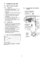
11.1 Select The Best Location
11.1.1 Indoor
Unit
•
Do not install the unit in excessive oil fume area
such as kitchen, workshop and etc.
•
There should not be any heat source or steam
near the unit.
•
There should not be any obstacles blocking the air
circulation.
•
A place where air circulation in the room is good.
•
A place where drainage can be easily done.
•
A place where noise prevention is taken into
consideration.
•
Do not install the unit near the door way.
•
Ensure the spaces indicated by arrows from the
wall, ceiling, fence or other obstacles.
•
Recommended installation height for indoor unit
shall be at least 2.5 m.
11.1.2 Outdoor
Unit
•
If an awning is built over the unit to prevent direct
sunlight or rain, be careful that heat radiation from
the condenser is not obstructed.
•
There should not be any animal or plant which
could be affected by hot air discharged.
•
Keep the spaces indicated by arrows from wall,
ceiling, fence or other obstacles.
•
Do not place any obstacles which may cause a
short circuit of the discharged air.
•
If piping length is over the [piping length for
additional gas], additional refrigerant should be
added as shown in the table.
Example: For HE9***
If the unit is installed at 10 m distance, the quantity of
additional refrigerant should be 50 g …. (10-7.5) m ×
20 g/m =50 g.
11.1.3 Indoor/Outdoor Unit Installation
Diagram
Summary of Contents for CS-NE9NKE
Page 12: ...12 4 Location of Controls and Components 4 1 Indoor Unit 4 2 Outdoor Unit 4 3 Remote Control...
Page 13: ...13 5 Dimensions 5 1 Indoor Unit...
Page 14: ...14 5 2 Outdoor Unit...
Page 15: ...15 6 Refrigeration Cycle Diagram...
Page 16: ...16 7 Block Diagram...
Page 17: ...17 8 Wiring Connection Diagram 8 1 Indoor Unit...
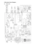
Page 19: ...19 9 Electronic Circuit Diagram 9 1 Indoor Unit...
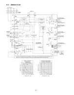
Page 20: ...20 9 2 Outdoor Unit...
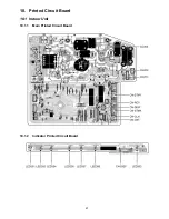
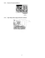
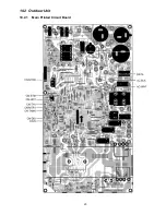
Page 23: ...23 10 2 Outdoor Unit 10 2 1 Main Printed Circuit Board...
Page 29: ...29...
Page 90: ...90 Figure 3 Figure 4 16 1 1 3 To remove discharge grille Figure 5...
Page 92: ...92 Figure 8 Figure 9...
Page 93: ...93 Figure 10...