


44
12.12.1.3 Judge Ambient Condition
•
According to sunlight intensity over a period of time, the system will analyze the ambient condition is sunny,
cloudy or night.
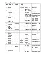
12.12.1.4 Temperature
Shift
Ambient condition
Sunny
Cloudy/
Night
Sunny
Cloudy/
Night
COOL/DRY Mode
Set Temperature
HEAT Mode
Set Temperature
-1°C
-1°C
+1°C
ECONAVI is activated while it is cloudy / night
ECONAVI is activated while it is sunny
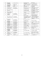
12.12.1.5 Sunlight Sensor Check Mode
•
To enable sunlight sensor check mode, during unit is OFF (power standby):
SET
SET
Transmit ECO demo code
and after 2 seconds return to normal
mode.
Press continuously for 15s
SET
Transmit check code
and after 2 seconds return to normal
mode.
SET
Transmit sunlight sensor check code
and after 2 seconds return to normal
mode.
Remote control normal mode
•
Operation
details
o
The sunlight sensor check mode will be operated for 5 minutes.
o
During check mode, the ON and OFF timer will be memorized but it operation be ignored.
o
During check mode, if the sunlight sensor check code is retransmitted, the 5 minutes counter will be reset.
o
During check mode, if sunlight sensor detected the sunlight intensity value above minimum level, the
ECONAVI indicator turns ON. Else if sunlight sensor detected sunlight intensity value below minimum level,
the ECONAVI indicator is OFF.
•
To disable sunlight sensor check mode
o
After check mode is ended (5 minutes counter elapsed), press AUTO OFF/ON button at indoor unit.
o
If the sunlight sensor detected sunlight intensity is at abnormal range, the check mode will be ended.
Please check for error code.
Summary of Contents for CS-NE9NKE
Page 12: ...12 4 Location of Controls and Components 4 1 Indoor Unit 4 2 Outdoor Unit 4 3 Remote Control...
Page 13: ...13 5 Dimensions 5 1 Indoor Unit...
Page 14: ...14 5 2 Outdoor Unit...
Page 15: ...15 6 Refrigeration Cycle Diagram...
Page 16: ...16 7 Block Diagram...
Page 17: ...17 8 Wiring Connection Diagram 8 1 Indoor Unit...
Page 19: ...19 9 Electronic Circuit Diagram 9 1 Indoor Unit...
Page 20: ...20 9 2 Outdoor Unit...
Page 23: ...23 10 2 Outdoor Unit 10 2 1 Main Printed Circuit Board...
Page 29: ...29...
Page 90: ...90 Figure 3 Figure 4 16 1 1 3 To remove discharge grille Figure 5...
Page 92: ...92 Figure 8 Figure 9...
Page 93: ...93 Figure 10...