


34
12.1.5 Automatic
Operation
•
This mode can be set using remote control and the operation is decided by remote control setting temperature,
remote control operation mode and indoor intake air temperature.
•
During operation mode judgment, indoor fan motor (with speed of Lo-) is running for 30 seconds to detect the
indoor intake air temperature.
•
Every 10 minutes, the indoor temperature is judged.
•
For the 1st judgment
o
If indoor intake temperature - remote control setting temperature
≥
2°C, COOL mode is decided.
o
If
-2°C
≤
indoor intake temperature - remote control setting temperature < 2°C, DRY mode is decided.
o
If indoor intake temperature - remote control setting temperature < -2°C, HEAT mode is decided.
•
For the 2nd judgment onwards
o
If indoor intake temperature - remote control setting temperature
≥
3°C, if previous operate in DRY mode,
then continue in DRY mode. otherwise COOL mode is decided.
o
If
-2°C
≤
indoor intake temperature - remote control setting temperature < 3°C, maintain with previous mode.
o
If indoor intake temperature - remote control setting temperature < -2°C, HEAT mode is decided.
12.1.6 Fan
Operation
•
Fan Operation is used to circulate air in a room.
•
During operation, indoor fan run continuously but outdoor fan and compressor stop.
•
Temperature setting is not applicable.
12.2 Indoor Fan Motor Operation
A. Basic Rotation Speed (rpm)
i. Manual Fan Speed
[Cooling, Dry, Fan]
•
Fan motor’s number of rotation is determined according to remote control setting.
Remote control
○
○
○
○
○
Tab Hi
Me+
Me
Me-
Lo
[Heating]
•
Fan motor’s number of rotation is determined according to remote control setting.
Remote control
○
○
○
○
○
Tab SHi
Me+
Me
Me-
Lo
Summary of Contents for CS-NE9NKE
Page 12: ...12 4 Location of Controls and Components 4 1 Indoor Unit 4 2 Outdoor Unit 4 3 Remote Control...
Page 13: ...13 5 Dimensions 5 1 Indoor Unit...
Page 14: ...14 5 2 Outdoor Unit...
Page 15: ...15 6 Refrigeration Cycle Diagram...
Page 16: ...16 7 Block Diagram...
Page 17: ...17 8 Wiring Connection Diagram 8 1 Indoor Unit...
Page 19: ...19 9 Electronic Circuit Diagram 9 1 Indoor Unit...
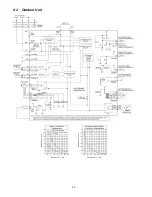
Page 20: ...20 9 2 Outdoor Unit...
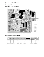
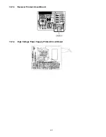
Page 23: ...23 10 2 Outdoor Unit 10 2 1 Main Printed Circuit Board...
Page 29: ...29...
Page 90: ...90 Figure 3 Figure 4 16 1 1 3 To remove discharge grille Figure 5...
Page 92: ...92 Figure 8 Figure 9...
Page 93: ...93 Figure 10...