


5
6
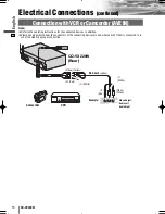
CQ-VX220W
English
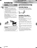
Installation
(continued)
1
3
5
6
2
4
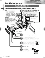
❏
Installation Procedures (When using Mounting Collar
w
)
Mounting the Main Unit
Insert the Mounting Collar
w
into the dashboard, and
bend the mounting tabs out with a screwdriver.
Establish the rear connection of the unit.
After fixing Power Connector
!0
,
fix the rear of the unit to
the car body by either method (a) or (b) shown at right.
Insert Trim Plate
q
.
After installation
reconnect the negative
(–) battery terminal.
Attach the Mounting Springs
e
to the unit.
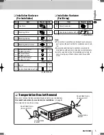
!0
Power Connector
r
Mounting Bolt
(5 mmø)
e
Mounting Spring
y
Flat-Head Screw
(5 mmø x 6 mm)
Note:
¡
The car model, installation condi-
tions and combination of the units
used may impose some restric-
tions on opening and closing the
monitor as well as on the angle
and position to which the monitor
can be adjusted.
Fastening the Mounting Collar
How much to bend the tabs will vary depending on the
car. Bend them with a screwdriver to fasten the
Mounting Collar
w
securely in the dashboard.
w
Mounting Collar
Dashboard
Tab
Insert the unit into Mounting Collar
w
.
Secure the clamp plate of Mounting Collar
w
to the hook of Mounting Spring
e
.
Clamp plate
IMPORTANT
When this unit is installed in dash-
board, ensure that there is sufficient
air flow around the unit to prevent
damage from overheating. Do not
block any ventilation holes on the
unit.
VX220W̲II̲01̲eng.qxd 09.2.24 7:21 PM ページ6
Summary of Contents for CQ-VX220W
Page 18: ...34 CQ VX220W Memorandum...
Page 19: ...35 CQ VX220W...