


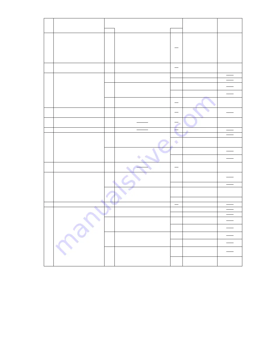
Component
Source of
problem
No.
Symptom
Troubleshooting
procedures
No.
Result
Main PCB
IC11
X2
RTC battery
2
2-1
Replace the Main PCB.
Date or Time cannot be
input.
Date and Time does not
change properly.
Date and Time are not
displayed.
Main PCB
IC5 ~ 8
IC4
3
3-1
Replace the Main PCB.
Memory count is too large
or too small.
YES
NO
Software setting
Go to No. 4-2
YES
NO
Speakers
Go to No. 4-3
4
4-1
4-2
Check software setting.
Replace the Speakers.
Does operation return to
normal?
Main PCB
IC7
IC10
4-3
Replace the Main PCB.
No Sound
Volume does not work.
12
NO
11
Configuration
Check configuration.
5-1
5
Default configuration in
use
Main PCB
IC11
6-1
6
Interrupt controller failure
Main PCB
7-1
7
Timer failure
Go to No. 8-2
Does the system return to
normal if the expansion card
is removed?
YES
Main PCB
NO
IC11
IC4
8-1
8
Expansion card ROM
checksum error
Expansion card
Replace the expansion card.
Does operation return to
normal?
YES
Main PCB
NO
8-2
Main PCB
IC11
9-1
9
Real Time Clock failure
Error during
SETUP
Battery
Main PCB
Does resetting through
SETUP correct the problem?
Replace the battery.
Does operation return to
normal?
YES
YES
NO
RTC battery
IC11
10-1
10-2
10
Dead RTC Battery
Go to No. 10-2
NO
Configuration
Check configuration.
11-1
Configuration error
Go to No. 12-2
Were the correct settings
selected during SETUP?
YES
Go to No. 12-4
12-1
CMOS Checksum error
FDD
Replace the FDD.
Does operation return to
normal?
YES
Go to No. 12-3
NO
12-2
HDD
Replace the HDD.
Does operation return to
normal?
YES
Go to No. 12-4
NO
12-3
Error during
SETUP
Does resetting through
SETUP correct the problem?
YES
Main PCB
NO
IC11
X2
12-4
14-2
Summary of Contents for CF-07 Series
Page 3: ... RU 8 6 1 2 2 ...
Page 4: ...2 3 ...
Page 21: ...9 6 System Memory Map ...
Page 24: ...8 Diagnosis Procedure Basic Procedures 11 ...
Page 41: ...Example ALT F brings up the File menu Input screen Order of test flow selection 16 5 ...
Page 43: ...14 Wiring Connection Diagram 17 ...
Page 47: ...16 Exploded View 1 Exploded View 1 2 19 1 ...
Page 48: ...2 Exploded View 2 2 19 2 ...
Page 64: ......
Page 65: ......
Page 66: ......
Page 67: ......
Page 68: ......
Page 69: ......
Page 70: ...CF 07LZ5ZYXM 1 Schematic Diagrams Upper Main 1 CPU 1 2 ...
Page 71: ...Upper Main 2 CPU 2 2 2 ...
Page 72: ...U s 3 pper Main 3 Resister ...
Page 73: ...U k 4 pper Main 4 Cloc ...
Page 74: ...U 5 pper Main 5 GMCH M 1 2 ...
Page 75: ...pper Main 6 GMCH M 2 2 U U 6 ...
Page 76: ...pper Main 7 ON Board Memory 7 U U ...
Page 77: ...pper Main 8 Micro DIMM 8 U U ...
Page 78: ...Upper Main 9 iCH2 M 1 2 9 ...
Page 79: ...Upper Main 10 iCH2 M 2 2 10 U U ...
Page 80: ...pper Main 11 Terminator 11 U U ...
Page 81: ...U Upper Main 12 HDD 12 ...
Page 82: ...Upper Main 13 BIOS 13 U U ...
Page 83: ...Upper Main 14 PCMCIA Controller 14 ...
Page 84: ...pper Main 15 Slot 1 WLSD Connector 15 U U ...
Page 85: ...pper Main 16 LED Connector 16 U ...
Page 86: ...Upper Main 17 Base Connector 17 ...
Page 87: ...Upper Main 18 VCPUCORE VC25 18 ...
Page 88: ...pper Main 19 Power Circuit 19 U U ...
Page 89: ...Upper Main 20 Modem Controller 20 ...
Page 90: ...pper Main 21 Line Codec 21 U U ...
Page 91: ...Lower Main 1 Connector 22 L L ...
Page 92: ...ower Main 2 Super I O 23 L ...
Page 93: ...Lower Main 3 COM Connector 24 L L ...
Page 94: ...Lower Main 4 Wireless Connector 25 L L ...
Page 95: ...Lower Main 5 KBC 26 L L ...
Page 96: ...Lower Main 6 Q AW for Doc 27 L L ...
Page 97: ...Lower Main 7 Doc Connector 28 ...
Page 98: ...Lower Main 8 EC 29 ...
Page 99: ...L LLower Main 9 Reset 30 ...
Page 100: ...L Lower Main 10 DC IN 31 ...
Page 101: ...L Lower Main 11 VD3 VD5 32 ...
Page 102: ...L Lower Main 12 Power Circuit2 33 ...
Page 103: ...L Lower Main 13 BATT SW 34 ...
Page 104: ...Lower Main 14 RF DC DC 35 ...
Page 105: ...Lower Main 15 Charger 36 ...
Page 106: ...Lower Main 16 Doc Power 37 ...
Page 107: ...Lower Main 17 VD18 38 ...
Page 108: ...Serial Connector 39 S S ...
Page 109: ...D U Sub Connector 40 D DDD ...
Page 110: ...D U Docking Connector 41 D DD ...
Page 111: ...D U Sub Connector 42 D D ...
Page 112: ...43 ...
Page 113: ...44 ...
Page 114: ...45 ...
Page 115: ...W W 46 ...
Page 116: ...Wireless 5 RF IF Mixer 1st Lo 47 ...
Page 117: ...48 ...