background image

38

Step 3

Press the [Enter] key on the keyboard.

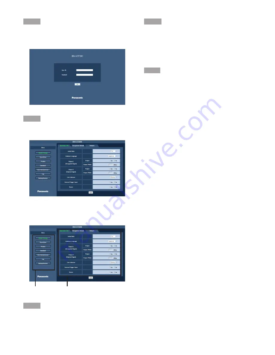
Login page will be displayed.

Step 4

Enter [User ID] and [Password].

Setup Menu will be displayed.

How to Operate the Setup Menu

Step 1

Click the desired button in the frame on the left of the win-
dow to display the respective setup menu.

Step 2

Complete each setting item displayed in the frame on the
right of the window.
When there are tabs at the top of the setup page displayed
in the frame on the right of the window, click the desired tab
to display and configure the setting items relating to the
name of the tab.

Step3

After completing each setting item, click the [Apply] button
to apply them.

Menu Buttons

Setup page

Summary of Contents for BMET200 - IRIS RECOGNITION

Page 1: ...ating Instructions Model No BM ET200 Before attempting to connect or operate this product please read these instructions carefully and save this manual for future use The model numbers in these Operating Instructions are given without suffix ...

Page 2: ...ersonnel or system installers The connection should be in accordance with the National Electrical Code NFPA70 and the local authorities having juris diction The exclamation point within an equilateral triangle is intended to alert the user to the presence of important operating and mainte nance servicing instructions in the litera ture accompanying the appliance CAUTION TO REDUCE THE RISK OF ELECT...

Page 3: ...ied by the manufacturer 10 Refer all servicing to qualified service personnel Servicing is required when the apparatus has been damaged in any way such as power supply cord or plug is damaged liquid has been spilled or objects have fallen into the apparatus the apparatus has been exposed to rain or moisture does not operate normally or has been dropped 11 All interconnecting devices must be UL Lis...

Page 4: ...ore mentioned reasons or other causes of such system except for the Product 6 ANY LOSS OR DAMAGE OR CLAIMS ARISING OUT FROM LOSS OR LEAK OF PC DATA INCLUDING IRIS DATA IN THE IRIS SERVER PC IC CARD OR MEMO RY Iris data is nature of privacy The customer shall be responsible for any Iris data stored in the iris server PC 7 INCONVENIENCE OR ANY LOSS ARISING WHEN IMAGES ARE NOT DISPLAYED DUE TO ANY RE...

Page 5: ...by restricting users to those who log in with an authorized user name and password Apply measures such as user authentication to protect your network against leakage or theft of information including iris data authentication information user names and passwords and alarm mail information Trademarks and Registered Trademarks Microsoft Windows Windows Server ActiveX and Internet Explorer are either ...

Page 6: ...nfigure the Settings Relating to User User Administrator 41 Check the Logs Log 45 Back up or Restore Files 48 Configure the Settings Relating to Time and Date Time Date 50 Check the Version of Iris Reader Software Version 50 Download Files Download 51 Operations from the Numeric Key For Use with Stand Alone Mode Only 53 Setup Network Mode 63 Connection and Setup Flow 63 Registering Administrators ...

Page 7: ...ions for compatibility with the UL Listed card readers and compatibility with the BM ET200 As an enrollment iris reader for iris image capturing and iris server enrollment To activate iris recognition it is necessary to capture the iris images of a user and enroll the iris data in the iris server An iris reader generates iris data from iris images captured and transfers the data to the iris server...

Page 8: ...can be distributed from the iris server to iris readers If the iris data of user has been distrib uted to a recognition iris reader or if a card reader connected to a recognition iris reader reads the iris data out of a card the iris reader can recognize the user in approx 0 3 seconds after iris image capturing 2 The user can check the recogni tion result with the result indicator accept reject on...

Page 9: ...ognition time will be approx 5 seconds after iris image capturing 2 1 The recognition time may differ depending on capturing conditions 2 The recognition time may differ depending on the traffic of the network or the total number of the enrolled users Option camera can be installed BM ETC202 Not supplied to the iris reader Optional minisize color camera can be installed in the iris reader You can ...

Page 10: ...nel for how to turn on off the power Note While the power is turned off recognition and entrance will NOT be available This unit must be powered by a UL Listed access control power limited power supply capable of 4 hours of standby power Adopting tamper proof structure Refer to service personnel for relocating or servicing the apparatus As the unit has been designed in tamper proof struc ture buzz...

Page 11: ...ders Take care not to pinch your hands or fingers between the front panel and the body of this appara tus That may cause injury When the front panel is damaged refer to the dealer It may affect iris image capturing and cause invalid recognition Avoid placing a receptacle that contains liquid such as water When the liquid falls over the apparatus it may cause a fire or electric shock Follow all ins...

Page 12: ...r between each person Iris server PC in which the following applications are installed The iris server can administer all the iris readers connected in the LAN Administration Software BM ES200 User Licence Software BM EU30000E Series Interface board Board that is connected to external devices supporting the Wiegand RS 485 interface When the iris reader is used in the stand alone mode the Wiegand R...

Page 13: ...d administrator can control the web browser In the stand alone mode at least one user with the operator s privi lege must be enrolled through the web browser control Numeric key control Setting change and control of iris reader can be performed with the numeric key Numeric key control is available in the stand alone mode only Administrator User that is allowed web browser control The administrator...

Page 14: ... setup guide These manuals are intended for system installers and administrators Normally users of recognition iris readers do not have to read them When using this iris reader in the network mode system installers and administrators should read the following manual as well as this document To use Administration Software BM ES200 BM ES200 Operating Instructions These manuals are PDF documents cont...

Page 15: ... When a user comes to the posi tion that is most suitable for capturing all the five lamps light up w Front panel Eye image capturing cameras and a near infrared light are located behind this panel Depending on the user the near infrared light blinking red light can be seen Notes Avoid covering the front panel with a hand or cloth etc That may cause invalid enrollment recognition Avoid pinching ob...

Page 16: ...nal devices High speed serial interface is only used in the stand alone mode and the stand alone mode has not been evaluated by UL Rear View Remove the cable hole cover by loosening the screws with a Phillips screwdriver Reinforcing screw holes Mounting screw holes Tamper detection lever Cut off from the rear cover Cable hole cover Used if you lay cables along a wall surface 2 High speed serial in...

Page 17: ...200 Operating Instructions supplied to Administration Software BM ES200 for details on communication setup 17 ON 1 2 3 4 ON 1 2 3 4 Cable hole Power terminal Connector terminal q 1 q 2 q 3 q 4 Interface board w 11 w 12 w 13 w 14 w 15 w 16 w 17 w 18 w 19 w 20 w 1 w 2 w 3 w 4 w 5 w 6 w 7 w 8 w 9 w 10 Setup switches Connector CN6 Connector CN7 Cable hole Option camera screw holes LAN connector 10BASE...

Page 18: ...T A signal RS 485 A is input from or output to a card reader OUT A signal DATA0 is input from a card reader to this terminal 0 V to 5 V DC 25 mA Max Active low DATA 0 RS 485 B card reader Wiegand RS 485 B IN OUT A signal RS 485 B is input from or output to a card reader Differential input 0 2 V or more Differential output 2 V or more When termination is ON OUT A signal DATA0 is input from a card r...

Page 19: ...ut from or output to an access control panel Differential input 0 2 V or more Differential output 2 V or more When termination is ON IN A signal DATA0 is out put from this terminal to an access control panel 0 V to 5 V DC 25 mA Max Active low w 6 w 7 GND access control panel Wiegand RS 485 Not used The iris reader works even when nothing is connect ed to this terminal GND POWER access control pane...

Page 20: ...OUTPUT 2 REJECT RLT2 RECOGNITION RESULT OUTPUT 2 GND REJECT GND OUT This terminal is activated when recognition is not successfully completed 24 V DC 24 mA Max Open collector output Normally Open contact Active low Pulse width 0 1 s to 60 s ALARM OUTPUT 1 POWER STATUS GND GND Pin No ALARM OUTPUT 1 POWER STATUS ALM1 OUT This terminal is closed and low when power is supplied from an external power s...

Page 21: ...ur rent setting Set this switch to ON when the IP address that has been set is forgotten Static IP address is assigned IP address set by an administrator Static IP address 192 168 0 3 OFF OFF Not used Set this switch to OFF any time Operation Selects the operation mode Stand alone mode Network mode Factory default OFF Start up Resets the software to the factory default Factory default soft ware Op...

Page 22: ...mmunication may not be established Setting name Function ON OFF Remarks SW1 3 SW1 4 OFF Not used _ Do not set Factory default _ OFF Not used _ Do not set Factory default _ SW2 1 SW2 2 OFF Communication I F 2 access control panel Wiegand RS 485 Factory default OFF Communication I F 1 access control panel Selects the interface for connection with access control panel Determines the func tions of w 7...

Page 23: ...s camera supports auto negotiation When a switching hub supporting auto sensing are used auto detect may not activate properly and the connection may not be established w 1 w 2 w 3 w 4 w 20 w 19 w 16 w 15 w 14 w 13 w 12 w 11 w 8 w 9 w 10 Power terminal Card reader 2 Wiegand DATA1 w 10 Wiegand DATA0 w 9 Wiegand GND w 8 Access control panel 2 Wiegand DATA1 w 4 Wiegand DATA0 w 3 Wiegand GND w 2 Wiega...

Page 24: ...c When using with the external storage device a USB hub is neces sary UL style 1571 or equivalents AWG 22 16 Shielded cable or shielded wire must be used Remove 9 mm 10 mm of the outer jacket of the cable and twist the cable core to prevent the short circuit first Recommended tool Flat blade screwdriver ø3 mm x 2 6 mm W ø0 12 x 0 1 W UL style 1571 or equivalents AWG 22 16 Shielded cable or shielde...

Page 25: ...tored in the reader If the iris camera is left in the tamper detection status for a specified period the iris data stored in the iris reader will be deleted The tamper detection status can be canceled with Setup Switch 8 Set this switch to ON when the front cover is removed for servicing Refer to p 21 After servicing set this switch to OFF and close the front cover The iris reader becomes the oper...

Page 26: ...ion Noise for example places near air conditioners or ventilators Electricity When objects made of glass or acrylic etc are located between an iris reader and a user enrollment or recognition may fail due to the light refraction light reflection or sensor malfunction Installation Space and Recognition Range Keep the Installation Space The installation space described in the following illustrations...

Page 27: ...lows Note If your eye position is higher than the upside limit bend down If your eye position is lower than the downside limit get on a pedestal etc 0 12 mm 0 47 in 300 mm 12 in 400 mm 15 7 in 1 678 mm 66 1 in Upside limit of the eye position 1 395 mm 54 9 in Center of optical axis Recommended installation height 1 240 mm 48 8 in Bottom of the iris reader unit 45 Side View ...

Page 28: ...unting Otherwise it may cause dropping trouble or injury Check if the wall has enough strength for mounting and no dents Otherwise the tamper detection mode will be activated Important Do not bury this iris reader into the wall Heat may not be released fully and that may cause malfunction If necessary use reinforcing screw holes When the cables are lead out of the bottom side cut off the fixed por...

Page 29: ...rmly Otherwise that may cause loose connection or cable disconnection Do not mistake signal terminals and GND terminals 10 Connect the interface board to the iris reader Important Wiegand and RS 485 interfaces are avail able in the network mode only In the stand alone mode these interfaces are unavailable 1 Insert the interface board into the connector firmly until the connector clicks 2 Fix the i...

Page 30: ...or cable disconnection Do not mistake signal terminals and GND terminals 12 Connect the earth to the GND terminal by using the earth ground cable supplied Secure the GND cables of iris reader and interface board together Caution Earth ground cable supplied must be con nected to the earth ground 13 If necessary connect the option camera not supplied to the iris reader with the BNC cable supplied to...

Page 31: ...f numeric key to the high speed serial interface The numeric key control is avail able in the stand alone mode only 17 Detach the protection film from the front panel The front panel is covered with the protection film for preventing damage Be sure to detach the film after the installation process of the iris reader High speed serial interface ...

Page 32: ...lege Maximum number of administrators 3 Maximum number of log information System log 1 000 Access log 10 000 When the saved system logs or access logs reach the maximum number the older logs will be deleted chronologically Available External Devices This iris reader can be connected with the following external devices External storage device USB Mass Storage Class compliant FAT32 file format Numer...

Page 33: ...peration Info OK External trigger input set ting Reader Setting Operation Info OK Buzzer setting User Reader Setting Operation Info OK Register iris data User Administrator User List OK OK OK Register PIN User Administrator User List OK OK OK Delete user information Delete all user informa tion Give an operator privi lege User Administrator User List User Administrator User List OK OK OK Delete PI...

Page 34: ... log to a CSV file Log Access Log OK OK OK Setting Item Log Delete all access log information Log Access Log OK OK OK Outputs the system log to a CSV file Log System Log OK OK OK Delete all system log information Log System Log OK OK OK Back up Restore User information Backup Restore User OK OK OK Reader setting Backup Restore Reader Setting OK OK OK Others Time date Network setting Reader Setting...

Page 35: ...ers with the operator s privilege Refer to p 37 Set up the operation information and recognition method Refer to p 40 Turn off the power supply Detach the front cover and remove the LAN cable Attach the front cover to the iris reader Connect the numeric key to the iris reader and supply the power to the iris reader Register users with the numeric key Shift from the recognition mode to the administ...

Page 36: ... the right of the window User ID Enter a user ID Available characters for the user ID Alphanumeric charac ters 0 9 A Z a z Upper and lower case letters are distinguished 6 to 16 1 byte characters can be entered Password Confirm password Enter the password Available characters for the user name Alphanumeric char acters 0 9 A Z a z Upper and lower case letters are distinguished 6 to 16 1 byte charac...

Page 37: ...ight of the window User ID Enter a user ID 01 to 99 can be entered PIN Confirm PIN Enter the PIN 0000 to 9999 can be entered Operator s Privilege Select Yes Step 4 Capture the iris data by clicking the Capture button Refer to p 44 Step 5 Click the Register button Settings are registered and the registration of user with operator s privilege is completed Setup from the Web Browser on the PC In the ...

Page 38: ...the win dow to display the respective setup menu Step 2 Complete each setting item displayed in the frame on the right of the window When there are tabs at the top of the setup page displayed in the frame on the right of the window click the desired tab to display and configure the setting items relating to the name of the tab Step3 After completing each setting item click the Apply button to appl...

Page 39: ...n the Version page Refer to p 50 Download button Click this button to display the Download page Software and audio file can be downloaded on the Download page Refer to p 51 User Administrator button Click this button to display the User Administrator page Users and administrators can be checked on the User Administrator page Registration of users and administrators are also available Refer to p 41...

Page 40: ...a pulse signal from the Output 1 Recognized Signal terminal at successful recog nition Either Yes or No is selected for setting Default No Output Width Setup becomes possible when Yes is selected with Output 1 Recognized Signal The selected output width after multiplied by 100 ms as a pulse signal is sent out from the Output 1 Recognized Signal terminal at successful recognition Available value 1 ...

Page 41: ...able Default Iris Recognition Only Check the User List User List Click the User List tab on the User Administrator page Refer to pages 37 and 38 It is possible to check the user information on this page Refer to p 42 for how to register users New button Registers the user Refer to p 42 Delete button Check the Delete checkbox es and click the Delete button The selected user s is are deleted Select ...

Page 42: ...out when not setting the PIN Operator s Privilege When Yes is selected operator s privilege is given to the user Iris Data Enrolled or Unenrolled is displayed Click the Capture button to capture iris image Step 3 Click the Register button The user data is registered Note Click the Cancel button to cancel registration Register Users User List Click the User List tab on the User Administrator page R...

Page 43: ...inistrator List tab on the User Administrator page Refer to pages 37 and 38 The following is how to register an administrator Step 1 Click the New button The Administrator screen is displayed Step 2 Complete each setting item displayed in the frame on the right of the window User ID Enter a user ID Available characters for the user name Alphanumeric char acters 0 9 A Z a z Upper and lower case let...

Page 44: ... eyes Note Click the Cancel button to cancel capturing Step 4 Click the Verify button to verify the result The result of verification is displayed in Result When the verification is valid Verified will be dis played When the verification is invalid Could not be verified will be displayed Step 5 When the verification is valid the Back button will become available Click the Back button to return to ...

Page 45: ... Back button Displays the previous page Next button Displays the next page No The serial number that shows the number of log informa tion Time and Date Displays the time and date of log information Example 06 01 23 13 59 59 ID Displays the user ID when recognition is accepted Result Displays the recognition result Top button Returns to the top of this page Note Up to 1 000 access log information c...

Page 46: ...l number that shows the number of log informa tion Time and Date Displays the time and date of log information Example 2006 01 23 13 59 59 ID For operation log information ID of user that performed operation is displayed User operating by the web browser control User ID of administrator 4 digit User operating by the numeric key control User ID 2 digit For alarm log information ID is not displayed ...

Page 47: ... the Log page Refer to pages 37 and 38 The following is how to output the access log or system log information to a CSV file Notes Time and Date User ID and Result are output to an access log CSV file Details on information output to a system log CSV file differ depends on codes Code 0 00 to 1 21 Operation log Operation time ID code C operation details Code A 01 to A 20 Alarm log Occurrence time c...

Page 48: ...le screen is displayed Step2 Select a file to restore and click the Open button File name bin Step3 Click the Execute button The following message is displayed Step4 Click the OK button to perform iris recognition Refer to p 73 When recognition is accepted restoration is started Back up user information Step1 Click the Execute button The following message is displayed Step2 Click the OK button to ...

Page 49: ...t a file to restore and click the Open button File name bin Step3 Click the Execute button The following message is displayed Step4 Click the OK button Restoration is started Back up reader settings Step1 Click the Execute button The following message is displayed Step2 Click the OK button The Save As screen is displayed Step3 Specify the folder and enter the name of file Then click the Save butto...

Page 50: ...and date display area Synchronized Time Date with PC button The acquired time and date from the PC will be registered in the iris server The acquired time and date are displayed as YY MM DD in the time and date display area drop down menu Note It is possible to set Second by clicking this button Configure the Settings Relating to Time and Date Time Date Configure the settings relating to time and ...

Page 51: ...lect the download file Select the ET200_ bin file STEP3 Click the Open button The selected file name is displayed in Download Software STEP4 Click the Execute button Download is started Download the Audio File Click the Audio File tab on the Download page Refer to pages 37 and 38 Perform audio file download on this page Step 1 Click the Browse button The Choose file screen is displayed Step 2 Sele...

Page 52: ...r the subnet mask of iris reader as nnn nnn nnn nnn Available value for nnn 0 to 255 Default 255 255 255 0 Gateway IP Address Enter the gateway IP address of iris reader as nnn nnn nnn nnn Available value for nnn 0 to 255 Default No setting Configure the Settings Relating to Network Network Click the Network tab on the Reader Setting page Refer to pages 37 and 38 Configure the settings relating to...

Page 53: ...eader will return to the recognition mode In this case retry the operation Shift from the Administrator Mode to the Recognition Mode The following is how to shift from the administrator mode to the recognition mode Note If no operation has been performed for 30 seconds or more the voice guidance will say Registration has been failed and the iris reader will return to the recognition mode In this c...

Page 54: ...completed Only right eye image is captured Only left eye image is captured Select verify or retry Verify the recognition result Press 0 enter The voice guidance will say Verifying iris data Capture the left eye Press 1 enter Capture the right eye Press 2 enter Capture the both eyes Press 3 enter Verify the recognition result The voice guidance will say Registration has been completed Notes When th...

Page 55: ...d Note When the voice guidance says Registration has been failed the iris reader will return to the status before operation Enter the PIN 4 digit again Example When the PIN is 1234 press 1 2 3 4 enter The voice guidance will say Registration has been completed Notes When you register the PIN of another user repeat Step 2 to 4 When the voice guidance says Registration has been failed retry Step 2 W...

Page 56: ...ic sound PiPi is heard Enter the ID 2 digit of a user to give the operator s privilege Example When ID is 01 press 0 1 enter The voice guidance will say Registration has been completed Notes When you give the operator privilege mode to other users repeat this step When the voice guidance says Registration has been failed the iris reader will return to the status before operation When finishing ope...

Page 57: ...3 No Procedure accept reject accept reject accept reject accept reject Delete the Operater s Privilege from Users The following is how to delete the operator s privilege from a user Delete a User The following is how to delete a user No Procedure Press 0 1 enter The short electronic sound PiPi is heard Enter the ID 2 digit of a user to delete Example When the ID is 01 press 0 1 enter The voice gui...

Page 58: ...file name is the time and date when the log is saved Refer to p 78 for details on log information No Procedure Press 0 6 enter The short electronic sound PiPi is heard When outputting the log information to a CSV file connect an external storage device and a numeric key with the USB hub to the iris reader Enter one of the following Output the access log information to a CSV file Press 0 enter Dele...

Page 59: ... Before restoring reader setting save a file as SystemInfo bin in the external storage device If this file does not exist it is impossible to restore the reader setting The name of file that is saved when backup is performed becomes SystemInfo bin No Procedure Press 0 7 enter The short electronic sound PiPi is heard Connect an external storage device and a numeric key with the USB hub to the iris ...

Page 60: ...ter The voice guidance will say Registration has been completed Note When the voice guidance says Registration has been failed retry Step 2 1 2 accept reject accept reject accept reject No Procedure Press 0 4 enter The short electronic sound PiPi is heard Enter one of the following Mute Press 0 enter Simple Press 1 enter Full Prres 2 enter Note When the voice guidance says Registration has been fa...

Page 61: ...Chinese Press 0 8 enter Korean Press 0 9 enter Arabic Press 1 0 enter Portuguese Press 1 1 enter Turkish Press 1 2 enter Dutch Press 1 3 enter Swedish Press 1 4 enter The voice guidance will say Registration has been completed in the selected lan guage Note When the voice guidance will say Registration has been failed retry Step 2 1 2 accept reject accept reject accept reject Select a Guidance Lan...

Page 62: ...PiPi is heard Select the recognition method When performing iris recognition only press 0 enter When performing iris recognition and PIN recognition press 1 enter The voice guidance will say Registration has been completed Note When the voice guidance says Registration has been failed retry Step 2 1 2 accept reject accept reject accept reject ...

Page 63: ...ader is used in the network mode Detach the front cover from the iris reader Refer to p 28 Make sure that the power is not supplied to the iris reader Perform the setup switch setting Set the operation mode to the network mode Attach the front cover to the iris reader Refer to p 31 Supply the power to the iris reader Perform the following settings using the web browser on the PC Register administr...

Page 64: ...eway IP Address No setting Refer to p 43 for how to register administrators Notes In the network mode registration of users with the operator s privilege is not required When changing the reader ID from the factory default setting refer to p 65 Setup from the Web Browser on the PC In the network mode iris reader setup is available from the web browser Notes Web browser control is available by admi...

Page 65: ...istrator List page Main area Pages of each setup menu will be displayed Reader ID IP Address Refer to p 52 Server IP Address Enter the IP address of iris server as nnn nnn nnn nnn Available value for nnn 0 to 255 Default 192 168 0 2 Note nnn nnn nnn 255 is unavailable Subnet Mask Gateway IP Address Refer to p 52 Configure the Settings Relating to System Reader Setting Click the Reader Setting butt...

Page 66: ...f the window Notes Refer to p 42 for details on setting items In the network mode iris registration by the web brows er control is unavailable Step 3 Click the Register button The administrator data is registered Note Click the Cancel button to cancel registration Check the Administrator List Administrator Click the Administrator button to display the Administrator List page It is possible to chec...

Page 67: ...with a cloth When light is reflecting on the lenses it may cause invalid iris image capturing In this case move your face or the iris reader s front panel upward or downward to avoid reflec tion If you still cannot recognize yourself take off your glasses sunglasses If you are wearing contact lenses With this iris reader you can carry out iris enrollment recognition wearing contact lenses However ...

Page 68: ...distance indicator will light up at the center of the mirror Notes The recognition range is within approx 30 cm to 40 cm 0 98 ft to 1 32 ft away from the iris reader The recognition area differs depending on users However the approximate recognition area is where you can stand holding the tilt handles with your arms bent moderately Make sure that you can see either eye in the mirror When the eyes ...

Page 69: ... a little Please move a little closer If You Have Difficulty in Eye Positioning When trying the procedure of How to Position Your Eyes in the Mirror p 68 you may sometimes have difficulty in positioning the eyes in the mirror In this case cover either eye and position your opened eye over an eye image capturing camera Note Even if you carry out one eye adjusting capture left and right eye separate...

Page 70: ...rs when you carry out enrollment In some cases you may need to retry capturing when enrolling your iris data Wait until you can confirm the capturing result Depending on the settings by the system administrators voice guidance may not be output The iris reader transfers the data to the iris server Then the data is enrolled in the iris server If there are no suitable images the iris server will dis...

Page 71: ... operators as it will take approx 10 seconds until the recognition result is output Follow the direction by the system administrators or operators 6 7 8 9 10 No Procedure accept reject How to Carry Out Enrollment Stand alone Mode The following is how to control the iris reader when your the user s iris data is enrolled in the iris reader Notes Follow the direction of system administrators or opera...

Page 72: ...he distance between the iris reader and you is too short the voice guidance will say Please move back a little When your eyes are positioned within the capturing range all the five lamps will light up the short electronic sound PiPi will be heard and your eyes will be captured Keep your eyes opened widely during your iris image capturing Capturing is finished The short electronic sound PiPi is hea...

Page 73: ... your face so as your eyes are positioned within 50 cm 1 64 ft from the iris reader The voice guidance will say Please look into the mirror The distance indicator or voice guidance will start 1 2 No Procedure accept reject accept reject Position your eyes in the mirror by referring to How to Position Your Eyes in the Mirror p 68 Move your position slowly by following the distance indicator or voic...

Page 74: ...ed by the user information such as the ID data etc Recognition by an Iris Reader and a Card Reader Stand Sit down in front of the iris reader Follow the directions by system administrators or operators Pass a card through the card reader Note If the card reader is a non contact type position the card close to the card read er Move your face so as your eyes are positioned within 50 cm 1 64 ft from ...

Page 75: ... refer to the system administrators or users with the operator s privi lege Depending on the settings by the system administrators voice guidance may not be output Note If no operation has been performed for 30 seconds or more the iris reader will return to the status before operation In this case retry the operation The following is how to carry out the PIN recognition using the numeric key Note ...

Page 76: ... is pressed operations performed since the ENTER key has been pressed last time can be canceled In the following example the password of User ID 12 is changed from 3456 to 7890 Press 1 0 enter When the input is valid the short electronic sound PiPi is heard When the input is mistaken the voice guidance will say Registration has been failed and the iris reader will return to the status before opera...

Page 77: ...pleted When the input is mistaken the voice guidance will say Registration has been failed and the iris reader will return to the status before operation 5 accept reject accept reject No Procedure ID may be invalid deleted not registered or the PIN recognition may be not allowed etc ...

Page 78: ...nformation is complete 0 20 Restore of reader information is complete Saved when restore of reader information is complete 0 21 Logged in Saved when an operator has logged in the setup menu 1 00 PIN was updated Saved when the PIN was updated 1 01 Changed Reader to Administrator mode Saved when a user has shifted from the recognition mode to the administrator mode 1 02 Changed Reader to Recognition...

Page 79: ...rson may have accessed the iris reader A 11 An unauthorized person may have accessed the reader unit A person may have accessed the iris reader with an improper item instead of the person s iris A 12 The reader unit may have been removed or the cover may be open Check if the iris reader is installed properly and if the cover is open A 13 The reader tamper detection function has been disabled Check...

Page 80: ...t open your eyes widely enough during captur ing You may have moved quickly during capturing If you move quickly that may cause invalid capturing Move slowly by following the distance indicator or voice guidance Light has been reflecting on the glasses Light reflection may cause invalid recognition Move your face or the front panel upward or down ward to prevent the reflection If you still cannot ...

Page 81: ...yes or not opened your eyes widely during capturing You were wearing sunglasses whose lens color is too deep to be captured Smudges were sticking on the glasses You were not looking at the mirror during capturing Your position is too near or too far from the iris reader to be captured When you come within approx 50 cm 1 64 ft of the iris reader the guidance will start The recognition range between...

Page 82: ...wearing sunglasses whose lens color is too deep to be captured Smudges were on the glasses You were not looking at the mirror during capturing Your position is too near or too far from the iris reader to be captured Refer to pages 68 and 80 The audio level of voice guidance may be set to the minimum The voice guidance may be set to Mute by the administration software Refer to system administrators...

Page 83: ... 25 mA Max Active low Wiegand DATA1 input card reader 0 V to 5 V DC 25 mA Max Active low RS 485 A B card reader Differential input 0 2 V or more Differential output 2 V or more When termina tion is ON 6 Interface access control panel Wiegand RS 485 Either can be selected Wiegand power input access control panel 5 V DC No connection available Wiegand DATA0 output access control panel 0 V to 5 V DC ...

Page 84: ...d party external power supply should meet the following specifications and must be powered by a UL Listed access control power limited power supply capable of 4 hours of standby power Rated ripple voltage Ripple noise 150 mV P P or less Overcurrent protection Enabled mandatory 2 This iris reader supports auto negotiation If you use a hub supporting auto sensing connection may not be established du...

Page 85: ...85 ...

Page 86: ...any of Panasonic Corporation of North America Security Systems www panasonic com security For customer support call 1 877 733 3689 Executive Office Three Panasonic Way 2H 2 Secaucus New Jersey 07094 Zone Office Eastern Three Panasonic Way Secaucus New Jersey 07094 Central 1707 N Randal Road Elgin IL 60123 Southern 1225 Northbrook Parkway Suwanee GA 30024 Western 6550 Katella Ave Cypress CA 90630 2...

Reviews: