9
1. Functions in each area
1-2. Crosspoint area
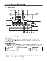
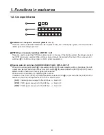
PGM/A bus crosspoint switches [PGM/A 1 to 7]
These are used to select the PGM/A bus video signals. In the case of the flip-flop system, the main line video
(PGM) signals are always selected.
PST/B bus crosspoint switches [PST/B 1 to 7]
These are used to select the PST/B bus video signals. In the case of the flip-flop system, the images inserted
next (PST) are always selected. When a B bus crosspoint switch is pressed while one of the source selector
switches (
6
) is held down, key signals or AUX signals are selected.
6
Source selector switches [SOURCE SELECT/AUX, KEY-S, KEY-F]
When a B bus crosspoint switch (
) is pressed while the [AUX] source selector switch is held down, the AUX
signals are selected, and when a B bus crosspoint switch (
) is pressed while the [KEY-S] or [KEY-F] source
selector switch is held down, the key signals are selected.
While a switch is held down, its indicator lights in amber.
In addition, if the [CLN], [PVW] or [PGM] wipe pattern selector switch (
7
) is pressed while the [AUX] switch is
held down, the switch will operate as an AUX bus selector switch.
[CLN]: Clean signals are output to the AUX bus.
See 3--
[PVW]: PVW signals are output to the AUX bus.
See 3--
[PGM]: PGM signals are output to the AUX bus.
See 3--
Summary of Contents for AVHS300G - HD SWITCHER
Page 55: ...55 8 Appearance Unit inch mm 16 1 8 410 9 1 2 240 4 1 16 103 5 3 16 5 ...
Page 61: ...Memo ...
Page 62: ...Memo ...
Page 63: ......


