background image

– 123 –

Chapter 7 Menu Operations — Menu list

Item

Description of settings

Remark

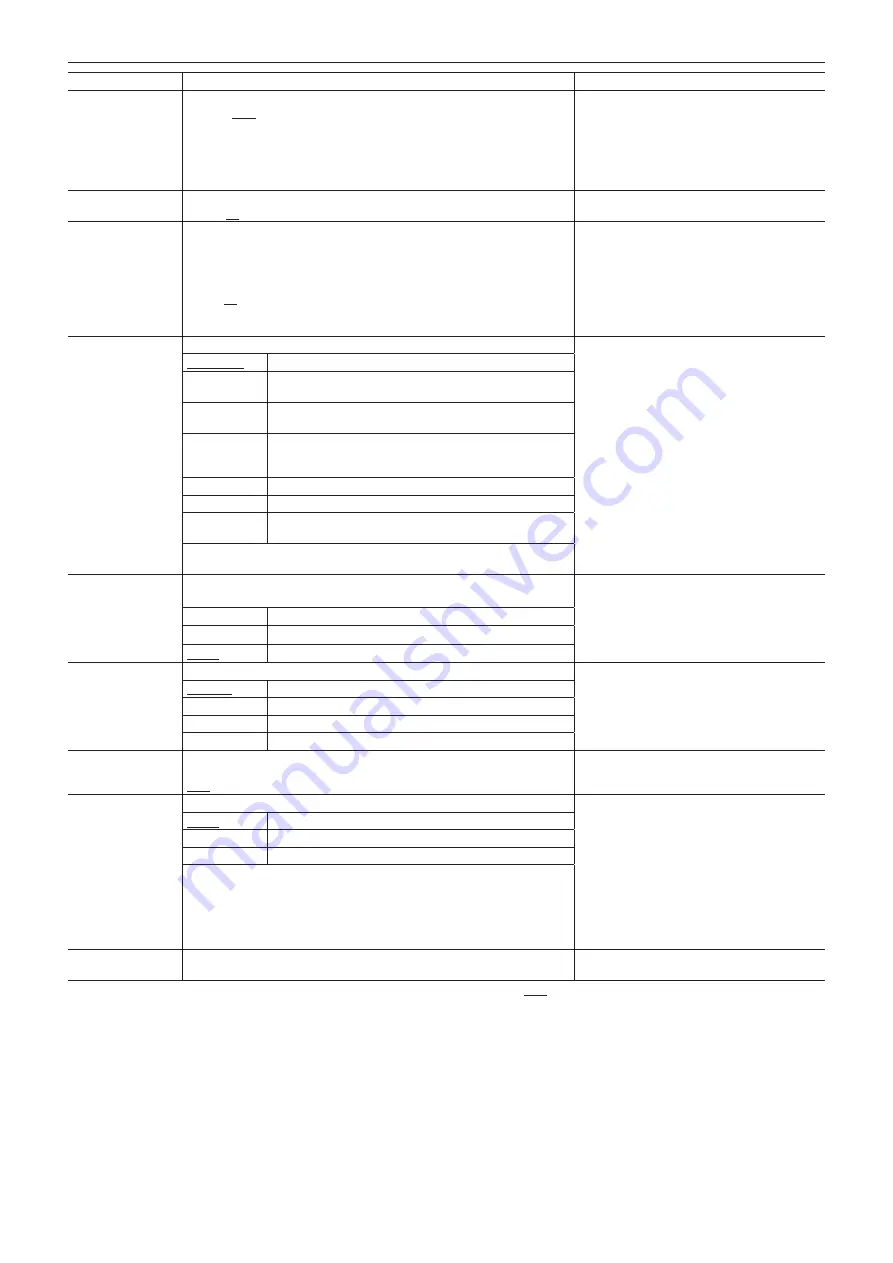
MASTER PED

Adjusts the master pedestal (black level of the image) as the basis for images.

[

100] ... [

+

12] ... [

+

100]


f

Press and turn up or down the jog dial button, 

and keep pressing it at the position to change the 

value faster.


f

When the remote control unit (AJ-RC10G) or the 

extension control unit (AG-EC4G) is connected, 

make adjustments with the M-PED volume of the 

remote control unit or the extension control unit.

A. IRIS LEVEL

Sets the desired auto iris level.

[

10] ... [0] ... [

+

10]

DRS EFFECT

Sets the compression level for the high-brightness areas of the dynamic range 

stretcher function.

It enables the dynamic range to be expanded by compressing the level of the 

video signals in the high-brightness areas where overexposure results during 

normal shooting.

[1], [2], [3]


f

The higher the value of the setting, the higher the compression level of the high-

brightness areas and the level of noise in dark areas.


f

When 1080i and progressive mode are set, the 

dynamic range stretcher function is not activated 

even if [DRS EFFECT] is set.


f

Set the [AUTO KNEE SW] item on the [SW 

MODE] screen is set to [DRS] and push the 

<OUTPUT>/<AUTO KNEE> selector switch 

towards the <ON> side to activate the dynamic 

range stretcher function.

GAMMA

Selects the gamma curve.


f

While the dynamic range stretcher function is 

activated and when the [CAMERA] item is set to 

[CINE-LIKE], images are not changed even if the 

setting is changed.

[HD NORM]

Suitable for HD shooting.

[LOW]

Makes a mellow image using a gamma curve that has a gentle 

incline in low-brightness curve. The contrast sharpens.

[SD NORM]

This is the normal video setting carried over from the DVX100 

series.

[HIGH]

Expands the tone of dark parts and makes a brighter image 

using a gamma curve that has a sharp incline in low-brightness 

curve. The contrast softens.

[B.PRESS]

Makes the contrast sharper than [LOW].

[CINELIKE D]

Uses a gamma curve designed to create cinema-like images.

[CINELIKE V]

Uses a gamma curve designed to create cinema-like images 

with emphasized contrast.


f

When you select [CINE-LIKE] gamma, we recommend setting the lens aperture 

lower than normal image level (approximately 1/2) for optimal results.

KNEE

To avoid overexposure, select the compression level (knee point) of the high 

intensity video signals received through the MOS sensor.


f

While the dynamic range stretcher function is 

activated, images do not change when the setting 

is changed.


f

To set the knee point automatically according 

to the signals received, use the <AUTO KNEE> 

switch.

[HIGH]

High setting (Compression starts at approx. 100%)

[MID]

Medium setting (Compression starts at approx. 90%)

[LOW]

Low setting (Compression starts at approx. 80%)

MATRIX

Selects the matrix table suitable for the desired color expression during shooting.

[NORM1]

Suitable for shooting in the open air or under a halogen lamp.

[NORM2]

Suitable for brighter colors than the [NORM1] mode.

[FLUO]

Suitable for shooting under fluorescent lights indoors.

[CINE-LIKE]

Suitable for shooting cinema-like images.

SKIN TONE DTL

Switches skin tone details [ON]/[OFF].

Select [ON] to reduce the skin tone details and soften the skin tone.

[ON], [OFF]

V DETAIL FREQ

Sets the vertical detail.

[THIN]

Makes the detail thin.

[MID]

Makes the detail slightly thick.

[THICK]

Makes the detail thick.


f

When images shot with the [THIN] or [MID] setting in progressive mode are 

played back on a usual TV monitor (60i: interlaced), you will sense flicker on 

horizontal lines and nearly-horizontal diagonal lines. When playing back in 

progressive environment, or performing post-processing such as edit, set this 

item to [THIN] or [MID] to obtain images with higher resolution than the images 

of [THICK] setting.

NAME EDIT

Edits the name of the scene file selected on the [CAM02:SCENE FILE] screen of 

SmartUI.


 indicates the factory setting value of scene file number F1.

Summary of Contents for ag-hpx600ej

Page 1: ...the instructions carefully and save this manual for future use ENGLISH VQT4L06A M0812YY0 YI Register now ヵㄉㄊㄔチㄑㄓㄐㄅㄖ ㄕチㄊㄔチㄆㄍㄊㄈㄊ ㄍㄆチㄇㄐㄓ ㄕㄉㄆチヱビラュチブチヺㄆ ㄓチヸ ㄓㄓ ㄏㄕㄚ ンㄆㄑ ㄊㄓチヱㄓㄐㄈㄓ ㄎハ ョㄐㄓチㄅㄆㄕ ㄊㄍㄔネチㄔㄆㄆチㄑ ㄈㄆチプハ ㄉㄕㄕㄑホババㄑ ㄏ ㄔㄐㄏㄊ ハ ㄊㄛバㄔ ㄗバㄑ ㄔㄔ ㄆバ Model No AG HPX600P Model No AG HPX600EJ Model No AG HPX600EN ...

Page 2: ...isk of fire or electric shock refer mounting of the optional interface boards to qualified service personnel CAUTION Do not jar swing or shake the unit by its handle while the conversion lens or another accessory is attached Due to the added weight of the conversion lens any strong jolt to the handle may damage the unit or result in personal injury CAUTION In order to maintain adequate ventilation...

Page 3: ...ay cause harmful interference to radio communications However there is no guarantee that interference will not occur in a particular installation If this equipment does cause harmful interference to radio or television reception which can be determined by turning the equipment off and on the user is encouraged to try to correct the interference by one of the following measures Reorient or relocate...

Page 4: ...onnel CAUTION Do not jar swing or shake the unit by its handle while the conversion lens or another accessory is attached Due to the added weight of the conversion lens any strong jolt to the handle may damage the unit or result in personal injury CAUTION In order to maintain adequate ventilation do not install or place this unit in a bookcase built in cabinet or any other confined space To preven...

Page 5: ...e core s they must be attached on cable s following instructions in this manual 3 Performance level The performance level of the apparatus is equivalent to or better than the performance level required by these standards However the apparatus may be adversely affected by interference if it is being used in an EMC environment such as an area where strong electromagnetic fields are generated by the ...

Page 6: ...tp panasonic biz sav pass_e Free 5 years of Warranty Repairs Customers who register as users on the website will receive an extended warranty repair valid for up to five years P2HD 5 Year Warranty Repair Program 1 Thank you for purchasing this Panasonic P2HD device Register as a user for this device to receive a special service warranty up to five years of free warranty repairs Make sure to save t...

Page 7: ...ks of their respective owners f f This product is licensed under the AVC Patent Portfolio License All other acts are not licensed except private use for personal and non profit purposes such as what are described below To record video in compliance with the AVC standard AVC Video To play back AVC Video that was recorded by a consumer engaged in a personal and non commercial activity To play back A...

Page 8: ... function 58 Setting the flash band compensation function 58 Assigning functions to USER buttons 60 Selecting audio input and adjusting recording levels 61 Selecting audio input signals 61 Adjusting the recording levels 61 Selecting F AUDIO LEVEL dial function 62 Setting the time data 63 Recording and output of time codes and user bits 63 User bits settings 66 How to input user bits 66 Setting the...

Page 9: ...ction to a computer in the device mode 146 USB host mode 146 Connecting to the remote control unit AJ RC10G 151 Connecting to the extension control unit AG EC4G 152 Chapter 10 Maintenance and Inspection 153 Inspections before shooting 154 Preparing to inspect 154 Inspecting the camera unit 154 Inspecting the memory recording functions 154 Maintenance 156 Charging the built in battery 156 Warning s...

Page 10: ...Before using the camera read this chapter and check its features and accessories Function extensions as extra cost options are also explained Chapter 1 Overview ...

Page 11: ... a data deletion program for computers commercially available to completely erase the data Users are responsible for managing the data stored in their memory cards r r Software information about this product f f This product includes software licensed under GNU General Public License GPL and GNU Lesser General Public License LGPL and customers are hereby notified that they have rights to obtain re...

Page 12: ...G This enables recording of the SDI signal input from the SDI OUT IN OP terminal f f Upgrade Software Key AG SFU601G Network function This enables addition of text memos from IT devices In explanations from here on this option is referred to as network function extra cost option f f Upgrade Software Key AG SFU602G Production pack This allows the following functions to be used to achieve substantia...

Page 13: ... f Equipped with optical ND filters at four positions r r Chromatic aberration compensation function CAC The camera is equipped with a function to automatically correct registration error that occurs mainly due to slight chromatic aberration etc which cannot be compensated on the lens itself and minimizes color smearing in peripheral images r r Remote control supported The remote control unit opti...

Page 14: ...e is no need to cue up blank area as you do for VTRs Recording can be started immediately even during a preview simply by pressing the REC button In the Normal mode recorded data is never lost by it being overwritten So you can be rest assured that your data is safe unless files are deleted or the card is initialized r r Other features f f Pre recording Critical moments that you might have missed ...

Page 15: ...o supported r r HDMI output Video can be output to a monitor compatible with the HDMI terminal f f The camera is not compatible with VIERA Link r r HD SD SDI input extra cost option By installing the HD SD SDI input board extra cost option SDI signals input from the SDI OUT IN OP terminal can be recorded Note however that only SDI signals in the same recording format as the camera can be recorded ...

Page 16: ...VRQDO FRPSXWHU 86 GHYLFH PRGH 9LD WKH 86 WHUPLQDO RQQHFWLRQ WR H WHUQDO HTXLSPHQW LQ 86 KRVW PRGH WHUQDO KDUG GLVN GULYH 86 KRVW PRGH 1 FDEOH FRPSRVLWH 6 0 FDEOH XGLR SLQ FDEOH 9LGHR HTXLSPHQW PRQLWRU 1 P2 cards and cables are optionally available They are not supplied with the camera 2 The USB 2 0 cable is not supplied with the camera Prepare a commercial USB 2 0 cable double shielded for noise s...

Page 17: ...RQLWRU 7 7 HWF LUHOHVV PRGXOH 0 9LGHR HQFRGHU ERDUG 6 6 LQSXW ERDUG HQV D RQHW W SH 8 121 121 7ULSRG DGDSWRU 6 1 70 9 PRXQW W SH EDWWHU SODWH 1 85 1 85 1 A battery holder is provided as standard on the main unit 2 For the latest information on P2 cards and SD memory cards not available in the Operating Instructions visit the support desk at the following website http pro av panasonic net 3 Refer t...

Page 18: ...age 99 Mount cap already attached to the product page 20 CD ROM f f Operating Instructions f f Utility software For installation procedures refer to the installation manual on the CD ROM NOTE t t After unpacking the product dispose of the packing material properly ...

Page 19: ...This chapter describes the names functions and operations of parts on the camera Details displayed on the HOME screen of SmartUI are also described Chapter 2 Description of Parts ...

Page 20: ...ng a battery of 90 Wh or more is recommended 9 Cable holders Used for clamping the light and microphone cables in place 10 Accessory mounting holes Attach accessories Do not use for purposes other than attaching accessories f f Mounting hole size 1 4 20 UNC screw length 10 mm or shorter 3 8 16 UNC screw length 10 mm or shorter 11 Shoulder strap fittings page 99 Attach the shoulder strap 12 Light s...

Page 21: ...eration of this control works on by the FRONT VR CH1 FRONT VR CH2 FRONT VR CH3 and FRONT VR CH4 items on the setting menu AUDIO SETUP screen 3 AUDIO IN CH1 3 AUDIO IN CH2 4 audio input channel 1 3 2 4 terminals page 98 Connect audio equipment or the microphone 4 LINE MIC line input microphone input selector switch page 98 Switch the audio input signal connected to AUDIO IN CH1 3 and AUDIO IN CH2 4...

Page 22: ... be monitored and during playback playback audio can be monitored Audio from the speaker is automatically turned off when an earphone is connected to the PHONES terminal 3 PHONES earphone terminal mini jack This is the terminal for connecting the audio monitor earphone stereo 4 AUDIO OUT terminal page 141 f f Output audio signals recorded on audio channel 1 2 or 3 4 f f Select output signals on th...

Page 23: ... the viewfinder screen turn off f f Push it towards the CHK side to display all information such as the setting status of the shooting functions and functions assigned to the USER buttons USER MAIN USER1 USER2 on the viewfinder screen during camera standby or shooting While the information is displayed push it towards the CHK side again to display the proxy and network setting status only when the...

Page 24: ...inal to CH1 2 or CH3 4 each time you press the button The channel display of the audio channel level meter is switched together When the screen other than the HOME screen of SmartUI is displayed the function corresponding to each setting screen is executed 12 REW rewind button Press this button during a pause to perform fast reverse playback Press it during playback to perform fast reverse playbac...

Page 25: ...perly if only the miniSD microSD adaptor is installed Make sure that the card has been inserted into the adaptor before use Use of Panasonic SD memory cards and miniSD microSD cards is recommended Be sure to format cards on the camera before use Any SD memory card with a capacity of 8 MB to 2 GB and any SDHC memory card up to 32 GB can be used on the camera Also when performing proxy recording ext...

Page 26: ...g and playback 4 EXIT CANCEL buttons page 105 Restore the display to the previous state while the thumbnail menu or property screen is displayed Also pressing this button with the SHIFT button held down makes it function as a cancel button which is convenient when batch canceling clip selections 5 Cursor SET button page 105 Operate the setting menu menu bars and thumbnails The four triangular butt...

Page 27: ...cking the time code of the external device to the time code on the camera page 70 3 HOLD button The time data indication on the counter display area is retained for the duration that this button is held down However the time code generator continues to advance Press again reactivates the counter This function is used to learn the time code or counter value of a particular recorded scene When the s...

Page 28: ... front tally lamp at the viewfinder 2 Rear tally lamp When the back tally switch is set to on the lamp acts in the same way as the back tally lamp 3 Back tally switch Control the action of the back and rear tally lamps ON The back and rear tally lamps are enabled OFF The back and rear tally lamps are disabled 4 WARNING lamp page 157 Start flashing or is illuminated if something unusual occurs in t...

Page 29: ...rame is displayed after converting the frame digit to 24 frames UB Indicates the user bits value FR Indicates the information of the frame rate at which recording is performed 60I 60i interlace mode 60 fields sec 60P 60P progressive mode 60 frames sec 30P 30P progressive mode 30 frames sec 24P 24P progressive mode 24 frames sec 24PA 24P advance mode 24 frames sec 50I 50i interlace mode 50 fields s...

Page 30: ...This chapter describes the basic procedure for recording and playback It also describes special photographic methods such as pre recording and interval recording Chapter 3 Recording and Playback ...

Page 31: ... Los Angeles 09 00 Tokyo 08 30 09 30 Darwin 09 00 Alaska 10 00 Guam 09 30 Marquesas Islands 10 30 Lord Howe Island 10 00 Hawaii 11 00 Solomon Islands 10 30 11 30 Norfolk Island 11 00 Midway Islands 12 00 New Zealand 11 30 12 45 Chatham Islands 12 00 Kwajalein Atoll 13 00 00 30 NOTE t t Clock accuracy is a lunar inequality of approximately 30 seconds with the power off t t When accurate time is req...

Page 32: ... viewfinder screen the camera gives out a warning indication by an alarm or WARNING lamp etc All P2 card access LEDs flash rapidly in orange so if this is the case turn off the power page 157 t t If the P2 card is removed while being accessed clips on it may become irregular Check the clips and restore them if required page 109 t t If the P2 card being formatted is removed formatting of the P2 car...

Page 33: ... card is not properly formatted Reformat the card FORMAT ERROR No card No P2 card is inserted The card is waiting to be recognized NO CARD The mode check is displayed on the viewfinder screen For details refer to Viewfinder status display page 72 P2 card recording time r r P2 cards supported on the camera Optional P2 cards with a capacity of 4 GB to 64 GB can be used with the camera As of Septembe...

Page 34: ...8 2 3 21 352 9 2 92 217 176 ULYH OO WKHVH IROGHUV DUH UHTXLUHG 7KLV LV WKH ILOH WR ZKLFK WKH LQIRUPDWLRQ RI WKH ILQDO FOLS WKDW ZDV UHFRUGHG ZLWK WKH 3 GHYLFH LV ZULWWHQ NOTE t t If even part of this information is modified or deleted the data may no longer be recognized as P2 data or the memory card may not longer be able to be used with P2 devices t t When transferring data from a P2 card to a c...

Page 35: ...is inserted later that P2 card will not be accessed until the previously inserted P2 card has been recorded to f f Example When P2 cards are inserted in two slots If both slots contain P2 cards the P2 cards are recorded in order slot number 1 2 However if the P2 card is slot number 1 is removed and then re inserted the P2 cards will be used in the following order slot number 2 1 1 2 Note that the ...

Page 36: ... adjust the white balance by the following steps 1 Press the AUTO W B BAL switch towards the AWB side to adjust the white balance page 53 2 Set the AUTO W B BAL switch towards the ABB side to adjust the black balance page 55 3 Press the AUTO W B BAL switch towards the AWB side to adjust the white balance again 3 Point the camera at your subject and adjust the focus and zoom 4 When using the electr...

Page 37: ...ormed 2 to 2 5x longer than that by pull down recording Even in native recording the rate for outputting camera images and playback images is 59 94 frames that are pulled down R H R H R H R H R H DPHUD VKRRWLQJ 31 SXOO GRZQ 5HFRUGLQJ DPHUD VKRRWLQJ 31 SXOO GRZQ 5HFRUGLQJ 9DOLG IUDPHV NOTE t t Recording starts from the top of a 5 frame cycle for 24P 24PA recording 4 frame cycle for 24PN native reco...

Page 38: ... when the recording mode is 24PN 25PN 30PN and the frame rate is 24 25 30 respectively Also the time code can be set to free run F RUN Standard variable frame rate recording pull down recording r r Setting example in the 720 59 94P mode 1 Set the REC FORMAT item on the setting menu SYSTEM SETUP screen to AVC I100 60P For details refer to Setting menu basic operations page 118 2 Set the VFR item on...

Page 39: ...EC FORMAT AVC I100 30PN AVC I50 30PN DVCPROHD 30PN 30 frames VFR OFF 1080 59 94i REC FORMAT AVC I100 30PN AVC I50 30PN DVCPROHD 60i CAMERA MODE 30P 720 50P REC FORMAT AVC I100 25PN AVC I50 25PN DVCPROHD 25PN 25 frames VFR OFF 1080 50i REC FORMAT AVC I100 25PN AVC I50 25PN DVCPROHD 50i CAMERA MODE 25P Only when the REC FORMAT item on the setting menu SYSTEM SETUP screen is set to DVCPROHD 60i or DV...

Page 40: ...oth and provide a high quality slow motion effect r r Standard settings for overcrank shooting Setting Recording frame rate SYSTEM MODE REC FORMAT VFR FRAME RATE 720 59 94P AVC I100 24PN AVC I50 24PN DVCPROHD 24PN ON Set to 25FRAME or more 25 to 60 frames 1080 59 94i AVC I100 24PN AVC I50 24PN 25 to 30 frames 720 50P AVC I100 25PN AVC I50 25PN DVCPROHD 25PN ON Set to 26FRAME or more 26 to 50 frame...

Page 41: ...menu basic operations page 118 2 Set the PREREC MODE item on the setting menu RECORDING SETUP screen to ON The following is displayed in the special recording display area of the viewfinder screen page 77 Recording in progress P REC illuminated Paused P PAUSE illuminated 3 Press the REC button Video and audio from the fixed amount of time is recorded f f In the following instances pre recording is...

Page 42: ...ing are disabled t t Audio is not recorded t t Data recorded in this mode data until the STOP button is pressed is grouped together into a single file t t Acceptance of other recording operations sometimes slows down when recording is continued by one shot recording Loop recording f f This function successively records to two P2 cards inserted in the P2 card slots f f When there is no more free sp...

Page 43: ...on in the menu or in the thumbnail display t t Combining to a clip cannot be stopped even by pressing the STOP or REC button on the remote control unit AJ RC10G and on the extension control unit AG EC4G Exiting the one clip recording mode Set the ONE CLIP REC item to OFF by menu operations Cueing to the start of the combined section of a clip A text memo can be automatically attached to the start ...

Page 44: ...ediately after pre recording or before and after continuous recording across two card slots that the P2 card is inserted into the vacant card slot When inserting a P2 card make sure that there is at least one minute of free space on the card to be recorded to NOTE t t Hot swap playback is not supported Rec review function f f After recording ends pressing the RET button on the lens automatically c...

Page 45: ...ayed as thumbnails thumbnails and time codes at text memo positions can be displayed and played back from text memo points and only required positions can be selected and copied page 107 Adding text memos 1 Assign text memos to the desired USER buttons USER MAIN USER1 USER2 or the RET button on the lens on the setting menu SW MODE screen For details refer to Setting menu basic operations page 118 ...

Page 46: ... point of the next clip cued state If the REW button is pressed with playback paused the clip being played back is paused at the start point of the clip currently being played back cued state NOTE t t When playing back or switching to the thumbnail screen immediately after removing or inserting the P2 card or the power is turned on it may take time to read the clip information During this time UPD...

Page 47: ...s such as adjusting white and black balance adjusting shooting functions such as flash band compensation FBC function assigning functions to the USER buttons USER MAIN USER1 USER2 and setting the time data Chapter 4 Adjustments and Settings for Recording ...

Page 48: ...be interrupted but this is not a malfunction List of recording formats and recording functions The table below shows the formats supported by the camera and recording functions r r Recording formats and recording playback times Capacity Recording format AVC Intra 100 AVC Intra 50 DVCPRO HD DVCPRO50 DVCPRO DV 64 GB 1 card Approx 64 min Approx 128 min Approx 64 min Approx 128 min Approx 256 min 2 ca...

Page 49: ... 480P 480 59 94i SD SDI 480 59 94p VBS 480P 480 59 94i VBS 480 59 94p 720 59 94P AUTO 1080i 720P 720 59 94p 720 59 94p HD SDI 720 59 94p 480i 480P 480 59 94i SD SDI 480 59 94p VBS 480P 480 59 94i VBS 480 59 94p 480 59 94i SDI 480P 480 59 94i 480 59 94i SD SDI 480 59 94p VBS 480P 480 59 94i VBS 480 59 94p 1080 50i AUTO 1080i 720P 1080 50i 1080 50i HD SDI 1080 50i 576i 576P 576 50i SD SDI 576 50p VB...

Page 50: ... DVCPRO HD 1080 50i 4ch 25P 1080 25P Over50i 2 2 Pull Down 1080 25PsF Over50i 2 2 AVC I100 50i AVC I50 50i Disabled ON 1 25P 1080 50i AVC I 100 AVC I 50 1080 50i VFR 4ch AVC I100 25PN AVC I50 25PN 1080 24PN Native VFR At 25P 25PN Native audio recordable Mute At 25P 4ch available DVCPROHD 50i 50i 1 25P 1080 50i DVCPRO HD 1080 50i VFR 4ch 25P Disabled Not available Setting SYSTEM MODE 1080 23 98PsF ...

Page 51: ... AVC I 50 720 50P VFR 4ch AVC I100 25PN AVC I50 25PN 720 25PN Native VFR At 25P 25PN Native audio recordable Mute At 25P 4ch available DVCPROHD 50P 720 50P At 50P 720 25P Over50P 2 2 Pull Down At 25P For other than above 720 50P VFR DVCPRO HD 4ch DVCPROHD 25PN 720 25PN Native VFR At 25P 25PN Native audio recordable Mute At 25P 4ch available Setting SYSTEM MODE 480 59 94i Recording format SDI OUT I...

Page 52: ...Video format Audio AVC I100 60P AVC I50 60P Disabled Disabled Disabled 720 60P AVC I 100 AVC I 50 720 59 94P 4ch DVCPROHD 60P DVCPRO HD Setting SYSTEM MODE 720 50P Recording format MON OUT terminal SDI OUT IN OP terminal REC FORMAT CAMERA MODE VFR FRAME RATE Video format Audio AVC I100 50P AVC I50 50P Disabled Disabled Disabled 720 50P AVC I 100 AVC I 50 720 50P 4ch DVCPROHD 50P DVCPRO HD Setting ...

Page 53: ...cording playback functions section page 23 3 Place the white pattern at a point where the light conditions match those for the light source for the subject and zoom in on the white pattern so that the white color appears in the screen A white object cloth or wall near the subject may also be used instead of a white pattern The illustration below shows the required size for the white space NOTE t t...

Page 54: ...h the Auto Tracking White Balance ATW function that automatically tracks the white balance of images according to the lighting conditions The auto tracking white balance function can be assigned to B of the WHITE BAL switch by setting the ATW item on the setting menu SW MODE screen to Bch The auto tracking white balance function can be assigned to the USER buttons USER MAIN USER1 USER2 For details...

Page 55: ... 1 Set the AUTO W B BAL switch towards ABB and then release it The switch returns to the central position with the black balance automatically adjusted 2 During an adjustment the following message is displayed on the viewfinder screen ABB ACTIVE 3 The adjustment is complete in several seconds and the following message is displayed ABB END The adjusted value is automatically stored in memory NOTE t...

Page 56: ...ingly open and the depth of focus will become shallower as the shutter speed is increased t t The screen might be disrupted when the synchro scan and shutter settings are changed t t Under lighting conditions using fluorescent lighting or other discharge tube horizontal stripes might appear on screen If this happens this can be improved by adjusting the shutter speed t t A subject that quickly cro...

Page 57: ... 30 0 1 249 8 24P 24PA 24PN mode 1 24 0 1 249 8 When SYNC SCAN DISP item on the setting menu DISPLAY SETUP is deg 3 0d to 360 0d f f The shutter speed may vary before and after SYSTEM MODE is switched f f When the variable frame rate is less than 12P the selection step becomes less precise f f Set the SYNC SCAN DISP item on the setting menu DISPLAY SETUP screen to deg to set and display as the shu...

Page 58: ... 1 SDI PROXY F B C 1 0 8 0 i AVC I100 ERR P 3 2K L T BOX 0 dB ND 1 8 3 ND 1 S E P 1 2 0 1 2 I P 2 S PO T F 5 6 3 5 9 5 9 FM 6 Z 6 6 0 2 4 PN DR S 4 1 2 1 1 2 3 C H C H C AC Z x 2 D 0 0 E X This is not displayed when the OTHER DISPLAY item on the setting menu DISPLAY SETUP screen is set to OFF NOTE t t When the flash strobe lights the following phenomena may occur but these are due to the flash ban...

Page 59: ...unction is forcibly turned off if the camera is changed to the mode where the flash band compensation function cannot be used To use the function again return to the mode where the function can be used and press the USER buttons USER MAIN USER1 USER2 to turn on the flash band compensation function f f Even if the flash band compensation function is activated the flash band compensation function te...

Page 60: ...MX2 D ZOOMX4 Assigns the digital zoom function Zooms in on the field angle by 2x 4x vertically and horizontally FBC Switches the flash band compensation function on off Y GET Assigns the function for displaying the brightness level of the frame area displayed near the center WFM Assigns the function for switching the waveform display Select the waveform display at the WFM item page 126 on the sett...

Page 61: ... channel are output with SDI signals Set audio related details on the setting menu AUDIO SETUP screen page 127 AUDIO SETUP FRONT VR CH1 FRONT VR CH2 FRONT VR CH3 FRONT VR CH4 MIC LOWCUT CH1 MIC LOWCUT CH2 MIC LOWCUT CH3 MIC LOWCUT CH4 OFF OFF OFF OFF OFF OFF OFF OFF PUSH MENU TO RETURN Adjusting the recording levels Adjust the recording level to audio channels 1 2 by the following procedure 1 Pres...

Page 62: ...tting menu AUDIO SETUP screen When the input signal is selected in the menu the F AUDIO LEVEL dial operation is enabled for that input signal f f The audio level when the F AUDIO LEVEL dial is at level 10 becomes the value set in the AUD01 LEVEL screen of SmartUI AUDIO SETUP FRONT VR CH1 FRONT VR CH2 FRONT VR CH3 FRONT VR CH4 MIC LOWCUT CH1 MIC LOWCUT CH2 MIC LOWCUT CH3 MIC LOWCUT CH4 OFF OFF OFF ...

Page 63: ...at the start of recording is recorded to the user bits of the clip metadata r r Date time real time f f The internal clock measures the year month day and time and can display these on the viewfinder screen and on the output video from the MON OUT terminal etc f f The internal clock is used for measuring the free run time code while the power is off and as the time and year month day data of the u...

Page 64: ...es Matched to recording TC at start of recording 30 frames second SDI IN DVCPROHD 60P AVC I100 60P AVC I50 60P R RUN F RUN 5 DF NDF 30 frames LTC is output TC 30 frames tc 24 frames 480 59 94i CAMERA DVCPRO50 60i DVCPRO 60i DV 60i 60i 30P R RUN F RUN 2 DF NDF 30 frames Same value as LTC except none at DV LTC is output None TC 30 frames tc 24 frames 24P 24PA R RUN F RUN 3 NDF fixed 30 frames SDI IN...

Page 65: ... recording 7 For free run the time code is slaved to the input TC of the TC IN OUT terminal However it cannot be slaved during recording Recording and output of user bits System setting state Recording UB Output UB SYSTEM MODE REC SIGNAL REC FORMAT CAMERA MODE FRAME RATE LTC UB VITC UB UB of TC IN OUT terminal 1 LTC UB of HD SDI 1 VITC UB of HD SDI 1080 59 94i CAMERA DVCPROHD 60i 60i 30P Following...

Page 66: ...ription USER Records internal user values User values can be set at UBG on the SET01 TC UB screen of SmartUI Setting values are held even when the power is turned off For details refer to How to input user bits page 66 TIME Records the time measured by the internal clock DATE Records the hour digit of year month day date time measured by the internal clock EXT Records the user bit values currently...

Page 67: ...ention of user bits in memory User bit settings are automatically saved in memory and are retained even if the power is turned off Frame rate information recorded to user bits If the frame rate value of video information to be shot and recorded based on the frame rate set by each item on the setting menu SYSTEM SETUP screen or by the FRAME RATE item option is recorded in the user bits it can be ed...

Page 68: ...nd to advance it in the non drop frame mode set to NDF Note however that the time code runs by NDF at all times in the 24P 24PA and 24PN modes 2 Use the HOME button to set the SmartUI screen to the HOME screen 3 Set the counter display to TC by the COUNTER button 4 Use the SETUP button to set the SmartUI screen to the SET01 TC UB screen 5 Set the TCG item to SET 6 Set the time code Time code avail...

Page 69: ...time code r r When locking onto an external signal Reference time code GENLOCK IN TC IN OUT Reference video signal NOTE t t As a reference video signal a composite video signal can also be input in addition to an HD Y reference signal t t When the system mode is set to 480i 576i SD and 720P input the composite video signal t t If the system mode is 720P the video signal generator lock is activated...

Page 70: ...enerator power supply on continuously connect an external power supply to the DC IN terminal and then remove the battery pack If the battery pack is removed first there is no guarantee that the time code will stay externally locked External synchronization of the camera unit while an external lock is active While an external lock is active the generator lock is activated on the camera unit by the ...

Page 71: ...utput 1080i 1080i HD SDI l 90H delay l Video output COMPOSITE 90H advance l l SDI output 1080i SD 480i HD SDI l 90H delay l Video output COMPOSITE 90H advance l l 720P SDI output 720P 720P HD SDI l 120H delay Video output COMPOSITE 120H advance l SDI output 720P SD 480i HD SDI l 120H delay l Video output COMPOSITE 120H advance l l 480i SDI output 480i SD 480i Disabled None l l Video output Counter...

Page 72: ...Mode check screen displays mode check function The camera settings and status can be displayed on the viewfinder screen Pushing the DISP MODE CHK switch on the camera towards the CHK side switches between two screens STATUS screen display PROXY NETWORK screen displayed only when the option is installed Each screen is displayed for approximately three seconds Pushing the DISP MODE CHK switch toward...

Page 73: ...X 0 dB ND 1 8 3 EX ND 1 S E P 1 2 0 1 2 I P 2 S PO T F 5 6 3 5 9 5 9 MF 6 0 0 Z 6 6 0 2 4 PN DR S 4 1 2 1 1 2 3 C H C H C AC Z x 2 A REC D 1 2 3 4 6 7 8 13 14 15 35 33 32 30 28 27 26 25 24 23 12 22 21 17 19 18 20 10 11 16 34 31 29 5 9 1 Time code display Every time you press the COUNTER button you switch to the following data or no display Counter Counter value recording mode only TC Time code val...

Page 74: ...cording to the status f f Auto white balance and auto black balance operation status f f Warning displays error displays f f Switch and button operation information For details refer to Information display in center page 77 6 System frequency display Displays system frequency 60 When the system frequency set by the SYSTEM MODE item on the setting menu SYSTEM SETUP screen is 59 94 Hz 50 When the sy...

Page 75: ...ting on the AUDIO SETUP screen is set to 18dB C H 1 18dB 0dB C H 2 r r When a monaural channel is selected on the AUD03 MONI screen of SmartUI The channel number that is not selected is not displayed The recording level of each channel is displayed with each level bar and this indicates that the audio channels to be output to speaker the PHONES and AUDIO OUT terminals are monaural C H 1 When audio...

Page 76: ...on CAC Displayed when the chromatic aberration compensation function is active Only when the mode check is performed 30 Battery charge level display This changes 5 4 3 2 1 as the battery charge level gets lower When there is no more battery charge left 2 1 flashes When the AC adaptor is used other than 5 may be displayed but this is not a problem r r Batteries that support the battery charge level...

Page 77: ...nformation display BOS Top of the stream From here playback in the reverse direction is not possible CANNOT PLAY Displayed when playback is not possible CARD ERR 1 CARD ERR 2 CARD ERR 1 2 P2 card error in slot of indicated number UPDATING Card information is being read CANNOT REC Displayed when recording cannot be started by pressing the REC button EOS End of the stream From here playback in the f...

Page 78: ... balance function is activated ATW ATW LOCK Displayed when the auto tracking white balance function is assigned if the WHITE BAL switch is set to B AUTO KNEE ON OFF Displayed when the AUTO KNEE selector switch setting was changed AWB ch ACTIVE Automatic white balance operation display AWB P3 2K AWB P5 6K AWB VAR K Displays the assigned color temperature when the WHITE BAL switch is set at the PRST...

Page 79: ...ecording and playback frame rate l l l l 15 Audio level meter l l LEVEL METER item 16 Audio recording not available l l 17 Shutter speed l l l l 18 Dynamic range stretcher DRS function l l l l 19 Iris l l l l 20 Auto iris control l l l l 21 Zoom position l l ZOOM FOCUS item 22 Focus control information l l ZOOM FOCUS item 23 ND filter l l l 24 Gain l l l l 2 25 WHITE BAL switch position l l l l 3 ...

Page 80: ...e RET button on the lens For details refer to Assigning functions to USER buttons page 60 RET SW page 125 3 Automatic white balance automatic black balance abnormal display Displays the status in the mode check when the automatic white balance and automatic black balance do not function correctly 4 Battery type display Displays the battery type currently selected for detection of the battery charg...

Page 81: ...reen is displayed OFF Does not display 90 Displays the range that can be displayed in most household TVs 4 3 Displays the position after the screen is adjusted by 4 3 aspect ratio 13 9 Displays the position after the screen is adjusted by 13 9 aspect ratio 14 9 Displays the position after the screen is adjusted by 14 9 aspect ratio NOTE t t When the SYSTEM MODE item on the SYSTEM SETUP screen is s...

Page 82: ... area EXPANDED Press the FOCUS ASSIST button to enlarge the central area of the screen by approximately 3x to make it easier to focus FOCUS ASSIST button EXPANDED f f In the enlarged display the status display and zebra pattern disappear and EXPANDED is displayed at the top of the screen NOTE t t Only the viewfinder screen is displayed enlarged t t The display is not enlarged with video output SDI...

Page 83: ... the USER buttons USER MAIN USER1 USER2 and pressing the assigned USER buttons USER MAIN USER1 USER2 Press the button again to return to the normal display f f The waveform and vector displays can be switched by the WFM item page 126 on the setting menu SW MODE screen f f This is not displayed while the focus assist function EXPANDED is activated f f The waveform display cannot be recorded ...

Page 84: ...5 81 7 216 VFUHHQ 6 1 ĺ 2 6 9 6 FDUG 1 7 2 6 9 3 3 3 3 1 NOTE t t When the MENU INIT item on the setting menu OTHER FUNCTIONS screen is executed all current operation status values and values saved on the camera of F1 to F6 and the current operation status values and values saved on the camera in user files can be batch returned to factory defaults However TIME ZONE settings cannot be returned to ...

Page 85: ...roplets f f Avoid charging with electricity Store the SD memory card with the card still inserted into the camera and with the slot cover closed Performing operations on SD memory cards Perform operations such as formatting an SD memory card write setting data to an SD memory card or read data on a memory card on the setting menu CARD FUNCTIONS screen CARD FUNCTIONS SCENE FILE USER FILE SD CARD FO...

Page 86: ... operation changes after recording completes Same applies when the VFR item or the F RATE item is changed by switching between F1 to F6 of scene files r r Factory settings F1 File suitable for standard shooting F2 FLUO File suitable for shooting factoring in the characteristics of fluorescent lighting e g indoor shooting F3 SPARK File suitable for SD shooting with resolution hue and contrast enhan...

Page 87: ...er PROCESSING is displayed the following message is displayed SAVE COMPLETED f f To return settings to their previously saved values after scene file settings have been changed select LOAD in step 2 and perform step 3 in the same way f f To return scene file settings to factory settings select INITIAL in step 2 and perform step 3 in the same way f f To save and read user file settings and return s...

Page 88: ...he jog dial button READ OK is displayed when reading is complete For user files perform the same operation as for scene files at the USER FILE item on the CARD FUNCTIONS screen Re reading files from an SD memory card Perform steps 1 to 2 select TITLE RELOAD in step 4 and select YES and then press the jog dial button to re read the file Adding titles to files 1 Perform steps 1 to 4 2 Turn the jog d...

Page 89: ...Before you use the camera mount the battery and lens following the procedures in this chapter The mounting of accessories is also described in this chapter Chapter 5 Preparation ...

Page 90: ...supply output terminal for lighting Anton Bauer battery Light control switch NOTE t t The Anton Bauer battery holder includes both a power supply output terminal for lighting and a light control switch which are convenient when installing light Contact Anton Bauer Inc for details on lighting systems 2 Insert the battery and slide it in the direction of the arrow Release lever NOTE t t To remove th...

Page 91: ...Connect the external DC power supply to the DC IN terminal of the camera DC IN terminal DC cord External DC power supply 2 Turn on the external DC power supply switch if there is an external DC power supply switch 3 Turn the POWER switch of the camera ON r r External DC power supply Connect after making sure that the output voltage of the external DC power supply is compatible with the rated volta...

Page 92: ...switch of the external DC power supply on before turning the POWER switch of the camera ON If the operations are performed in reverse the camera may malfunction because the external DC power supply output voltage rises too slowly t t When connecting batteries to the DC IN terminal set to BATTERY with the EXT DC IN SEL item on the setting menu BATTERY SETUP screen and set the battery type with the ...

Page 93: ...ustments For details refer to Flange back adjustment page 93 NOTE t t For handling the lens refer to the lens operating instructions t t When the lens is removed install the mount cap to protect the device Flange back adjustment If images are not clearly focused at both telephoto and wide angle positions during zoom operations adjust the flange back distance from the lens mounting surface to the i...

Page 94: ...d correctly Try white shading adjustment again after the image returns to normal Selecting white shading data 1 Select the SHADING SELECT item on the setting menu LENS SETUP screen and press the jog dial button For details refer to Setting menu basic operations page 118 LENS SETUP SHADING SELECT SHADING USER CAC CAC PROPERTY CAC CARD READ CAC FILE DELETE CAC FILE INIT IRIS GAIN OFF ON LENS PUSH ME...

Page 95: ... button 2 The SHADING ACTIVE message appears on the screen during the adjustment 3 When the adjustment is complete after a few seconds the SHADING OK message appears f f If an error message such as SHADING NG LEVEL OVER or SHADING NG LOW LIGHT appears readjust the aperture f f The adjusted value is automatically stored in the set memory USER1 USER2 or USER3 6 If the lens is equipped with extender ...

Page 96: ...n error message is displayed Perform either initialization of the chromatic aberration compensation file or read the chromatic aberration compensation file from the SD memory card again For details refer to Reading the chromatic aberration compensation file from the SD memory card page 96 Initializing the chromatic aberration compensation file returning to the factory settings page 97 Reading the ...

Page 97: ...al button The display changes to when deletion is complete CAC FILE DELETE 1 KJ10EX4 5B IRSD PS12 2 3 4 5 6 7 8 PUSH MENU TO RETURN CAC FILE DELETE CAC FILE NO 1 DELETE YES PUSH SET NO Initializing the chromatic aberration compensation file returning to the factory settings 1 Select the CAC FILE INIT item on the setting menu LENS SETUP screen and press the jog dial button For details refer to Sett...

Page 98: ...RONT W L REAR AUTO MANU FRONT Using a wireless receiver 1 Remove the cover to insert the wireless receiver and secure it with the screws 2 According to the audio channel to be recorded switch the input signal to W L on the AUD02 INPUT screen of SmartUI AUD02 INPUT CH3 4 IN LVL IN LVL CH1 FRONT W L W L REAR AUTO MANU CH2 FRONT REAR AUTO MANU When using a two channel wireless receiver select DUAL in...

Page 99: ... click Removing the camera from the tripod adaptor While holding the red lever down move the black lever in the direction of the arrow and slide the camera backward to remove it Red lever Black lever NOTE t t If the tripod adaptor pin does not return to its original position after the camera has been removed hold the red lever down and move the black lever in the direction of the arrow again in or...

Page 100: ... 100 Chapter 5 Preparation Mounting accessories Attaching the rain cover Using the SHAN RC700 rain cover Tighten the cord Secure with the surface fastener ...

Page 101: ...ng an LED to this terminal it is useful for shooting video when fixing the camera on a crane DC OUT terminal Connection example 1 2 3 4 LED Resistance start stop Cable connector HR10A 7R 4SC 73 Hirose Electric Co Recording 1 GND 2 TALLY OUT Open collector output on the camera side Tally lamp on Low impedance Tally lamp off High impedance 3 Recording start stop switch This is connected in parallel ...

Page 102: ...oices created from one shooting session together with additional information such as text memos and metadata are saved as clips You can play back and edit clips with the camera Chapter 6 Thumbnail Operations for Clips ...

Page 103: ...tadata from the SD memory card Thumbnail screens are configured as follows THUMBNAIL OPERATION PROPERTY ALL CLIP SELECTED CLIPS TEXT MEMO CLIPS SLOT CLIPS SETUP EXIT INDICATOR DATE FORMAT EXIT DELETE FORMAT REPAIR CLIP EXIT CARD STATUS CLIP PROPERTY EXIT THUMBNAIL SIZE THUMBNAIL INIT SAME FORMAT CLIPS RE CONNECTION COPY PLAYBACK RESUME DEVICES PROPERTY SETUP MARKED CLIPS DATA DISPLAY SLOT1 SLOT2 M...

Page 104: ...mber hard disk drive status Indicates on which P2 card the pointed clip is recorded The slot number of the P2 card that contains clips is indicated in yellow If the clips are recorded on multiple P2 cards all slot numbers of the P2 cards that contain the clips are indicated in yellow The slot numbers are indicated in white if they contain P2 cards When the following P2 card is inserted the slot nu...

Page 105: ... supports edit copying 15 Wide clip indicator Displayed for clips recorded with the 16 9 aspect ratio However it does not accompany clips in HD format 16 Thumbnail scroll bar Indicates which part of the whole thumbnail is currently being viewed 17 Remaining battery charge display Displays remaining battery level For details refer to Battery charge level display page 76 on the Viewfinder status dis...

Page 106: ...ter moves to the clip that was being played back regardless of where the playback started t t Press the PLAY PAUSE button again to start playback from the beginning of the clip under the pointer To continue to play back from where previously stopped turn the PLAYBACK RESUME setting in Setting the thumbnail display page 113 to ON Switching the thumbnail display The display can be switched so that o...

Page 107: ...o the thumbnail of the clip at the pointer position f f To delete a shot mark place the pointer again and press the USER buttons to which the shot mark recording function is assigned or the RET button on the lens USER MAIN USER1 USER2 buttons NOTE t t A shot mark can be attached during recording t t Add shot marks after recording stops to attach the shot mark to the most recently recorded clip For...

Page 108: ... and left buttons Y I then press the PLAY PAUSE button f f Playback will start from the time code position of the text memo where the pointer is located If the STOP button is pressed during playback or the playback has finished at the end of the clip then the thumbnail screen appears again with the pointer placed on the thumbnail of the text memo where the playback started f f While holding down t...

Page 109: ...TE t t To interrupt deleting press the SHIFT button EXIT button or the SET button to cancel the operation The already deleted clips cannot be restored even if the deletion process is aborted Restoring clips Restores clips that are defective as a result of sudden power down during recording or removal of the P2 card being accessed NOTE t t The clips with yellow defective clip indicators can be rest...

Page 110: ...d video and sound information is not copied only thumbnails clip metadata icons Voice Memo proxy and real time metadata t t When recording capacity on the copy destination is insufficient LACK OF CAPACITY is displayed and copying is not performed When clips to be copied include defective clips CANNOT ACCESS is displayed and copying is not performed When selected clips include a clip that has been ...

Page 111: ...date of the clip DEVICE Displays MANUFACTURER name of the device manufacturer SERIAL NO serial number of the device and MODEL NAME model name of the device SHOOT Displays SHOOTER name of the person who shot the video START DATE start date of shooting END DATE end date of shooting and LOCATION ALTITUDE LONGITUDE LATITUDE SOURCE PLACE NAME altitude longitude latitude and source of the information an...

Page 112: ...d or when setting disables recording of loaded clip metadata Same as CLIP NAME The COUNT value is indicated as a four digit number The COUNT value is incremented each time a new clip is captured if clip metadata has been read in and TYPE2 has been selected as the recording method The COUNT value can be reset using the following method Select META DATA PROPERTY from the thumbnail menu and select th...

Page 113: ...he card 3 When the following screen appears select YES using the cursor buttons and the SET button The selected P2 card is formatted NOTE t t Since data that is deleted by formatting cannot be restored be sure to check the data before executing formatting Formatting SD memory cards SD memory cards can also be formatted from the thumbnail screen With an SD memory card inserted into the camera perfo...

Page 114: ...em DATA DISPLAY THUMBNAIL SIZE Select the thumbnail displayed on the screen from either LARGE displaying thumbnail in 3 2 or NORMAL displaying thumbnail in 4 3 This item is set to NORMAL in the factory settings PLAYBACK RESUME Select a position to restart playback after stopping playback on the thumbnail screen using the STOP button ON Playback starts from the stop position OFF Playback starts fro...

Page 115: ...board operation is the same as Checking and modifying uploaded metadata page 111 f f The input window soft keyboard for modifying metadata is displayed f f Input characters from the keyboard to modify the metadata 4 Press the OK button on the keyboard The modified metadata is written on the clip and the screen returns to the metadata details window NOTE t t To delete each item in LOCATION shooting...

Page 116: ...sed memory capacity The used memory capacity of the P2 card is shown as a bar graph and percentage The bar graph indicator moves to the right as the used memory capacity increases The following displays may appear depending on the card status FORMAT ERROR An unformatted P2 card is inserted NOT SUPPORTED An unsupported card is inserted on the camera NO CARD No P2 card is inserted Use the cursor but...

Page 117: ...This chapter describes how to operate the camera menus the structure and details of the setting menu Chapter 7 Menu Operations ...

Page 118: ...Y SETUP PUSH MENU TO EXIT 3 Press the jog dial button to display the item to set SW MODE LOW GAIN MID GAIN HIGH GAIN ATW W BAL PRESET USER MAIN USER1 USER2 0dB 6dB 12dB OFF 3 2K Y GET BACK LIGHT TEXT MEMO PUSH MENU TO RETURN 4 With the jog dial button move the highlight to the item to be set SW MODE LOW GAIN MID GAIN HIGH GAIN ATW W BAL PRESET USER MAIN USER1 USER2 0dB 6dB 12dB OFF 3 2K Y GET BACK...

Page 119: ...TIONS screen you can restore the current user file menu setting to its factory setting Initializing SCENE FILE Among six scene files select the scene file to be initialized from the CAM02 SCENE FILE screen of SmartUI Then by selecting INITIAL on the LOAD SAVE INIT item of the SCENE FILE screen you can restore the setting value of the selected scene file to its factory setting f f Scene files other...

Page 120: ...e not introduced the corresponding items in the menu are grayed out and cannot be selected 0 1 0 18 6 1 6 67 0 6 783 6 02 5 25 1 6 783 8 2 6 783 1 287 6 6 67 0 02 5 6 1 23 5 250 7 0 5 02 6 1 5 9 56 63 7 219 6 783 2 1 0 1 1 7 35 6 7 86 5 86 5 5 7 6 0 872 1 6 5 81 7 21 21 6 27 7 0 17 59 7 0 67 57 35 5 02 21 3 5 67 57 7 7 0 02 7 02 8 02 2 6 9 1 7 9 5 23 5 0 5 7 23 6 1 6 1 7 3 6 1 52 6 1 7 9 9 7 9 7 2...

Page 121: ... 1 7 25 6 23 3 52 6 23 86 5 66 5 7 2 6 77 1 7 0 21 3 6 3 6 6 6 7 0 18 1 7 7 1 6 77 5 6 7 77 5 02 7521 1 5 7521 1 5 21 1 5 21 1 5 21 1 5 1 85 1 5 1 85 1 5 3 H 1 5 7 3 8 7 3 1 5 7 3 1 7 3 8 7 3 1 5 7 3 1 1 5 1 1 5 6 1 5 6 1 9 8 63 6 783 9 3 9 9 3 5 4 9 2 25 5 7 7 5 7 7 5 0 5 5 6 7 21 2 86 5 7 7 0 9 0 7 5 220 2 86 5 77 3 5 5 0 1 27 5 63 0 18 5 2817 5 9 7 3 For REC MODE REC MODE 1080 REC MODE 720 or R...

Page 122: ...5 26 27 28 30 32 34 36 40 44 48 54 60 720 50P Variable from 1 up to 50 frames 25 steps 1 2 4 6 9 12 15 18 20 21 22 23 24 25 26 27 28 30 32 34 37 42 45 48 50 SYNC SCAN TYPE Selects the synchro scan display setting sec deg SYNCHRO SCAN Displays the synchro scan shutter speed used for TV screen shooting Continuous pressing of the jog dial button turned up or down will accelerate the speed to change t...

Page 123: ...tness curve The contrast softens B PRESS Makes the contrast sharper than LOW CINELIKE D Uses a gamma curve designed to create cinema like images CINELIKE V Uses a gamma curve designed to create cinema like images with emphasized contrast f f When you select CINE LIKE gamma we recommend setting the lens aperture lower than normal image level approximately 1 2 for optimal results KNEE To avoid overe...

Page 124: ... I100 30PN AVC I100 24PN Recorded using the AVC I 100 codec 60i 30PN native recording and 24PN native recording are used for shooting and recording respectively AVC I50 60P AVC I50 30PN AVC I50 24PN Recorded using the AVC I 50 codec 60i 30PN native recording and 24PN native recording are used for shooting and recording respectively DVCPROHD 60P DVCPROHD 30PN DVCPROHD 24PN Recorded using the DVCPRO...

Page 125: ...f the GAIN switch 3dB 0dB 3dB 6dB 9dB 12dB HIGH GAIN Sets the gain value assigned to the H position of the GAIN switch 3dB 0dB 3dB 6dB 9dB 12dB ATW Assigns the auto tracking white balance function to the WHITE BAL switch page 54 f f When the WHITE BAL switch is set to the B position and this menu is set to Bch pressing the USER buttons USER MAIN USER1 USER2 to which the auto tracking white balance...

Page 126: ...frm 4frm 8frm 16frm 1s f f This setting is available only when the REC FUNCTION item is set to ONE SHOT INTERVAL TIME Sets the interval time for interval recording page 41 2frm 4frm 8frm 16frm 1s 2s 5s 10s 30s 1min 5min 10min f f This setting is available only when the REC FUNCTION item is set to INTERVAL START DELAY Delays the start of interval recording and one shot recording approximately one s...

Page 127: ...phone input W L Works for wireless input REAR Works for rear microphone input OFF Off for any input MIC LOWCUT CH2 Sets microphone low cut filter for CH2 The setting contents are the same as MIC LOWCUT CH1 OFF MIC LOWCUT CH3 Sets microphone low cut filter for CH3 The setting contents are the same as MIC LOWCUT CH1 OFF MIC LOWCUT CH4 Sets microphone low cut filter for CH4 The setting contents are t...

Page 128: ...requency response when the microphone low cut filter is used is between 200 Hz to 10 kHz IN OUT SEL screen Item Description of settings Remark SDI OUT Sets the video output from the SDI OUT IN OP terminal ON Outputs video from the output OFF Does not output video from the output SDI OUT CHAR Selects whether to superimpose characters to SDI OUT f f When the SYSTEM MODE item is 1080 23 98PsF charact...

Page 129: ...G to be recorded without delay VIDEO OUT Outputs images according to the delay of output images from the MON OUT and SDI OUT IN OP terminals indicates factory setting values DISPLAY SETUP screen Item Description of settings Remark EVF PEAK LEVEL Adjusts the peaking level of the viewfinder screen 7 0 7 EVF PEAK FREQ Adjusts the peaking frequency of the viewfinder screen LOW Sets the peaking frequen...

Page 130: ...RA10 PAG L96e TYPE A TYPE B BATTERY MODE Sets the near end AUTO Near end is set automatically with the battery selected with BATTERY SELECT MANUAL Sets the near end voltage manually HYTRON50 NEAR Sets the near end voltage of HYTRON50 Can be adjusted in 0 1 V units 11 0V 13 4V 15 0V HYTRON140 NEAR Sets the near end voltage of HYTRON140 Can be adjusted in 0 1 V units 11 0V 13 1V 15 0V DIONIC HC NEAR...

Page 131: ...Shading compensation off SHADING USER Sets the shading parameter for USER1 USER2 and USER3 of SHADING SELECT f f This setting is not available when the SHADING SELECT item is OFF CAC Sets whether to activate the lens chromatic aberration correction CAC function ON Activates when the chromatic aberration correction function activation is possible OFF Does not activate the chromatic aberration corre...

Page 132: ...f recorded images OFF Does not superimpose time code on recorded images STREAMING MODE OP1 OP3 Selects the proxy streaming function f f In the following cases proxy streaming function is not activated even if set this item to RTP or HTTP The P2 BROWSE item is OFF The REC MODE item for proxy is neither HQ 2CH MOV nor LOW 2CH MOV Proxy recording is set to be performed the REC MEDIA item is P2 or P2 ...

Page 133: ...amps on the body are not illuminated CHAR During recording with the camera the tally lamp on the viewfinder is not illuminated and the recording status is displayed only with text on the screen The front tally lamp or the tally lamps on the body are not illuminated f f The screen display for recording always appears regardless of the above settings CLOCK SETTING Sets the built in calendar date and...

Page 134: ...camera VUP FS File system for updating the camera CAM FPGA Camera FPGA configuration ROM BE FPGA BE FPGA configuration ROM PROXY SOFT Proxy board software version display OP1 PROXY FPGA Proxy board FPGA configuration ROM OP1 SDI IN FPGA FPGA configuration ROM of the SDI signal input board OP2 OPTION STATUS Indicates whether there is an optional board and displays activated status of the upgrade so...

Page 135: ...A new interface consisting of an LCD display and multiple switches It enables scene file setting audio input output setting time code setting and so on Chapter 8 Using SmartUI ...

Page 136: ...ress this button to return to the HOME screen f f While the HOME screen is displayed press this button to change the status information display at the bottom of the screen 6 KEY LOCK switch Slide to the right to lock the operations of all buttons of SmartUI Slide to the left to unlock Buttons for thumbnail operations will be locked as well 7 HOLD button COUNTER button RESET button MONITOR SEL butt...

Page 137: ... 137 Chapter 8 Using SmartUI Setting menu structure Setting menu structure 20 0 5 8 2 6 783 0 67 786 0 6 1 0 6 783 8 9 8 1387 8 021 6 7 7 8 6 7 021 0 250 7 6 7 021 0 6 783 6 7 ...

Page 138: ... REAR CH4 REAR SET01 SET R RUN TCG RST TCMD h min s frm F RUN TC UB SET02 MON HDMI FORMAT VBS 576 i L BOX MON D CON SQU AUTO CROP HDMI 1080 i 720P SET03 MON HDMI SETUP OFF OUT CHR ZBR ON OFF ON OFF ON SET04 LCD 3 33 RST BACK CONTRAST LIGHT AUD03 MONI CH3 4 SEL 1 SEL 2 CH1 ST CH2 ST MIX STEREO CH1 2 CAMO2 SCENE FILE FILE F1 READ EXEC F2 FLUO F3 SPARK F1 F5 CINE V F6 CINE D F4 B STR CAMO3 SETUP F RA...

Page 139: ...mpatible lens is attached Any number between 99 and 00 is displayed in the place of When the distance to the in focus subject becomes shorter the value decreases page 76 3 Displays the zoom position Z00 Z99 Z mm 4 Displays the auto iris settings and the iris F value BACK SPOT F OPEN CLOSE NC 5 Displays the white balance control mode and the color temperature ATW ATW LOCK Ach Bch P3 2K P5 6K VAR K ...

Page 140: ...cted item PLAY PAUSE button Increases the setting value of the selected item MONITOR SEL button Moves the item selection to the right When the item selection moves to the right edge it moves back to the left edge F RATE OP4 Sets the variable frame rate f f This setting is not available when the setting menu on the viewfinder screen is open f f Other conditions where the setting is not available ar...

Page 141: ...ation also switches the audio channels output to the speaker earphone and AUDIO OUT terminal The display channels for audio level meter and audio volume on the HOME screen also switch r r When audio channel 3 4 is selected REW button Decreases the audio volume value of audio channel 3 STOP button Decreases the audio volume value of audio channel 3 FF button Decreases the audio volume value of audi...

Page 142: ...annel 1 PLAY PAUSE button LVL Selects the method to adjust the recording level for audio channel 4 The setting contents are the same as audio channel 1 MONITOR SEL button CH1 2 Toggles the audio input setting screen between CH1 CH2 Setting contents that switch in coordination are the same as the AUD01 LEVEL screen AUD03 MONI Selects the audio to be output to the speaker the PHONES terminal and the...

Page 143: ...er than 24P 24PA continuous recording may fail FF button Decreases the setting value of the selected digit in the time code PLAY PAUSE button Increases the setting value of the selected digit in the time code COUNTER button TC UB Switches to the user bits setting screen RESET button RST Resets all time code setting values to 0 MONITOR SEL button Moves the selected digit in the time code to the rig...

Page 144: ...de Adds black bands at the top and bottom of the image SQU Squeeze mode Squeezes images horizontally SET03 MON HDMI SETUP Sets the output setting of the MON OUT and HDMI terminal REW button OUT Enables or disables the output from the MON OUT terminal ON OFF STOP button CHR Specifies whether characters are superimposed over the output from MON OUT HDMI and REMOTE terminals ON OFF This setting is di...

Page 145: ...Chapter 9 Connecting to External Devices ...

Page 146: ...o a computer via USB ensure that no other device is connected to the computer via USB t t When connecting the camera via USB do not eject the P2 card t t When USB is connected the P2 card access LED turns off when not accessed t t When the camera is operating in the USB device mode no recording playback operation or clip thumbnail operation is allowed t t When the camera is operating in the USB de...

Page 147: ... MAIN USER1 USER2 to which PC MODE is assigned If the thumbnail screen is displayed pressing the USER buttons USER MAIN USER1 USER2 does not exit the USB host mode Using the USB host mode Hard disk drives that can be used f f Hard disk drives that support USB 2 0 connection f f Storage unit that has Panasonic USB 2 0 interface For details on the compatible unit visit the support desk at the follow...

Page 148: ...ity of the hard disk drive is displayed at the upper section Unit GB The number of P2 cards saved on the hard disk drive is displayed at the bottom section 6 FREE CAP The free space in the hard disk drive GB is displayed 7 Partition number The partition number of the hard disk drive is displayed The partition number is on a single P2 card basis NOTE t t Up to ten numbers are displayed in the scree...

Page 149: ...ts f f A progress bar is displayed during a write operation To cancel writing press the SET button and select YES for the cancel confirmation f f COPY COMPLETED is displayed when writing completes NOTE t t To bypass verification at writing select HDD SETUP from the thumbnail menu and set VERIFY to OFF The time until writing completes shortens but no data writing verification is performed t t Selec...

Page 150: ...r to Reconnecting incomplete clips page 109 Notes when using a hard disk drive f f Use the hard disk drive including P2STORE in the following conditions Use the hard disk drive within its operational range such as temperature Do not place the hard disk drive in a location that is unstable or subject to vibration f f Some hard disk drives may not function properly f f A hard disk drive with the SAT...

Page 151: ...trol mode REMOTE terminal AJ RC10G NOTE t t When connecting and disconnecting the dedicated cable ensure that you turn the POWER switches of the camera and AJ RC10G to OFF t t Do not use any cable other than the AJ RC10G dedicated cable or dedicated optional cable Doing so may result in a malfunction t t The USER buttons USER MAIN USER1 USER2 and the MENU button do not activate during AJ RC10G con...

Page 152: ...tically enters the remote control mode REMOTE terminal AG EC4G NOTE t t When connecting and disconnecting the dedicated cable ensure that you turn the POWER switches of the camera and AG EC4G to OFF t t Do not use any cable other than the AG EC4G dedicated cable or dedicated optional cable Doing so may result in a malfunction t t The USER buttons USER MAIN USER1 USER2 and the MENU button do not ac...

Page 153: ...Inspect the various parts of the camera before recording This chapter explains the warnings and error messages displayed on the viewfinder screen Chapter 10 Maintenance and Inspection ...

Page 154: ...de and rotate the iris ring to check the manual iris adjustment 5 Set the iris back to automatic adjustment mode and check the followings by switching the GAIN switch setting to L M and then H f f The iris is adjusted for objects with same degree of brightness as the setting changes f f The gain value display on the viewfinder screen changes as the setting changes 6 If a lens with an extender is a...

Page 155: ...ss the AUDIO button to display the AUD02 INPUT screen of SmartUI 4 Set the IN item in CH1 CH2 to REAR 5 Turn the microphone to an audio source and confirm that the audio level display on the viewfinder screen or on SmartUI changes according to the audio volume You can check each channel by connecting one microphone to each channel Inspections for the clock time code and user bits 1 Set the user bi...

Page 156: ... than a half year the built in battery runs out and may appear on the viewfinder screen In that case connect an external DC power supply or a new battery and charge the built in battery by leaving the camera turned off for approximately four hours Set the date and time after the charge completes If is still displayed after charging the built in battery needs to be replaced Consult the shop of purc...

Page 157: ...ing is not possible due to corruption of the GENLOCK IN input signal and the recording is suspended temporarily The clip will be divided f f Recording resumes when the signal returns to normal However recording does not resume in interval recording one shot recording and loop recording Check the GENLOCK IN signal 7 Low wireless signal reception WIRELESS RF flashes in red Flashes four times every s...

Page 158: ...C Intra 50 the thumbnail cannot be modified in the text memo position Set the SYSTEM MODE item on the setting menu SYSTEM SETUP screen according to the clips CANNOT COPY Images cannot be copied Check the copy conditions CANNOT DELETE Images cannot be deleted due to contents version mismatch Match the device and contents version CANNOT FORMAT A P2 card problem or some other reason prevents formatti...

Page 159: ...rive P2 import because the P2 card is already recorded The copy operation cannot be performed because the target P2 card is not empty Format the card using a P2 device and try again LACK OF CAPACITY Not enough space left on the hard disk drive There is not enough space on the connected target so use a new hard disk drive or formatted hard disk drive HDD DISCONNECTED The hard disk drive is disconne...

Page 160: ...es displayed after logging in to PASS Other benefits are offered to registered customers For details refer to the PASS P2 Asset Support System site http panasonic biz sav pass_e 2 Check the version using the camera and apply the update Check the version of the camera on the setting menu DIAGNOSTIC screen and access the latest information about the firmware described in the following NOTE and then ...

Page 161: ...roxy video recording and high quality recording with the digital input from the SDI OUT IN OP terminal are available by installing an optional board to the camera Chapter 11 Additional Functions from the Optional Board ...

Page 162: ...proxy data recording mode when the 720P mode is selected Only in 720P mode For details on each mode refer to Recording modes and recording signals video audio page 163 STD 2CH MP4 SHQ 2CH MOV HQ 4CH MOV HQ 2CH MOV REC MODE SD Sets the proxy data recording mode in the SD mode only For details on each mode refer to Recording modes and recording signals video audio page 163 STD 2CH MP4 LOW 2CH MOV TC...

Page 163: ...mode LOW 2CH MOV cannot be set Recording the proxy data Set the REC MEDIA item to P2 or P2 SD and press the REC button to start proxy recording at the same time as recording of the sources Push the DISP MODE CHK switch towards the CHK side twice to display the proxy data recording information on the viewfinder screen Recording to the SD memory card To record the proxy data use Panasonic SD or SDHC...

Page 164: ...prox 135 min When SYSTEM MODE is 720 59 94P or 720 50P mode LOW 2CH MOV cannot be set These are reference values for continuous recording with Panasonic products The recording time may differ depending on the scene or the number of clips Proxy recording in one clip recording mode Proxy recording is possible even in the one clip recording mode Since proxy data is also grouped together in the same w...

Page 165: ...information of the recorded data is displayed AUDIO SAMPLING RATE Audio sampling rate information of the recorded data is displayed NUM OF AUDIO CH The number of audio channels of the recorded data is displayed Error displays about proxy data recordings If an error occurs during recording the proxy data check the entries in the following table and take necessary actions Error displays viewfinder s...

Page 166: ...ed during recording f f An error occurred in recording to the SD memory card Check the status of the SD memory card and insert a recordable card page 163 NO SD CARD or SD CARD PROTECTED Proxy data will not be recorded to the SD memory card but recording to the P2 card will be performed f f No SD memory card is inserted NO SD CARD f f The SD memory card is write protected SD CARD PROTECTED Check th...

Page 167: ...put signal Auto recording function f f SDI input settings To record the SDI input signal with the camera select SDI IN at the REC SIGNAL item on the setting menu SYSTEM SETUP screen For details refer to the REC SIGNAL item page 124 Item Description of settings REC SIGNAL Selects the input signal CAMERA Records the camera shooting signal of the camera SDI IN Records the SDI input signal from the SD...

Page 168: ...This chapter describes the dimensions specifications and connector signals Chapter 12 Specification ...

Page 169: ... H D Body only 144 mm 267 mm 350 mm 5 21 32 inches 10 1 2 inches 13 25 32 inches excluding protrusion Camera unit Pickup devices 2 3 type MOS 1 Lens mount 2 3 type bayonet ND filter 4 position CLEAR 1 4ND 1 16ND 1 64ND Gain settings 3 0 3 6 9 12 18 dB for 18 dB assign GAIN 18dB to the USER button Color temperature settings ATW ATW LOCK Ach Bch preset 3200 K preset 5600 K VAR 2400 K to 9900 K Shutt...

Page 170: ...1080 59 94i 1080 29 97p 1080 29 97pN 1080 23 98p 1080 23 98pA 1080 23 98pN 720 59 94p 720 29 97p 720 29 97pN 720 23 98p 720 23 98pN 480 59 94i 480 29 97p 480 23 98p 480 23 98pA 1080 50i 1080 25p 1080 25pN 720 50p 720 25p 720 25pN 576 50i 576 25p Recording and playback time AVC Intra 100 16 GB 1 approx 16 min 16 GB 2 approx 32 min 32 GB 1 approx 32 min 32 GB 2 approx 64 min 64 GB 1 approx 64 min 64...

Page 171: ...u 2ch supported AUDIO OUT terminal Pin jack 2 CH1 CH2 output 316 mV 600 Ω Speaker 20 mm diameter round 1 Other input output GENLOCK IN terminal BNC 1 1 0 V p p 75 Ω TC IN OUT terminal f f TC IN OUT menu IN BNC 1 0 5 V p p to 8 V p p 10 kΩ OUT BNC 1 2 0 0 5 V p p low impedance DC IN terminal XLR 1 4 pin DC 12 V DC 11 0 V to 17 0 V DC OUT terminal 4 pin DC 12 V DC 11 0 V to 17 0 V maximum output cur...

Page 172: ... AAC LC Linear PCM For details on recording modes refer to Recording modes and recording signals video audio page 163 Supported formats when the HD SD SDI input board AG YA600G is installed Weight Approx 13 0 03 lbs Dimensions W H D 70 mm 50 mm 7 mm 2 3 4 inches 1 31 32 inches 9 32 inches Video format complies to the AG HPX600P AG HPX600EJ AG HPX600EN video format HD 1080 59 94i 1080 50i 720 59 94...

Page 173: ...REG 12 V max 1 5 A Panasonic Parts No K1AY104J0001 Manufacturer Parts No HR10A 7R 4SC 73 Hirose Electric Co VF 1 UNREG 12V DC 12 V power AJ HVF21KG approx 0 35 A 2 UNREG 12V DC 12 V power 3 A9 0V DC 9 V power not used 4 VF PB GND Viewfinder PB signal GND 5 VF PR GND Viewfinder PR signal GND 6 VF Y Viewfinder Y signal output 7 VF Y GND Viewfinder Y signal GND 8 VF CLK Serial data clock pulse signal...

Page 174: ...ply for the wireless receiver 6 RX ON Power remote output for the wireless receiver 7 RF WARN RF warning input from the wireless receiver 8 RM5 Not used 9 RM4 Not used 10 SPARE 1 Not used 11 SPARE 2 Not used 12 EXT CLK Not used 13 CLK SHIELD Not used 14 CH 2 SHIELD GND 15 CH 2 HOT Audio input from the wireless receiver CH2 HOT 16 CH 2 COLD Audio input from the wireless receiver CH2 COLD 17 5 6 V P...

Page 175: ...ING 122 DETAIL LEVEL 122 DIAGNOSTIC screen 134 Dimensions 169 DIONIC90 NEAR 130 DIONIC160 NEAR 130 DIONIC HC NEAR 130 DISPLAY SETUP screen 129 DRS 13 DRS EFFECT 123 Dynamic range stretcher function 13 E Electronic shutter 56 ENDURA7 NEAR 130 ENDURA10 NEAR 130 Error displays 77 158 EVF COLOR 129 EVF PEAK FREQ 129 EVF PEAK LEVEL 129 EVF TYPE 129 EXT DC IN SEL 130 External DC power supply 91 External...

Page 176: ...4 REC FUNCTION 126 REC MEDIA 132 162 REC MODE 720 132 162 REC MODE 1080 132 162 REC MODE SD 132 162 Recording format 48 Recording function 48 Recording functions 41 Recording levels 61 RECORDING SETUP screen 126 Rec review function 44 REC SIGNAL 124 167 REC TALLY 133 Remote control 151 RET SW 125 R MIC CH1 LEVEL 128 R MIC CH2 LEVEL 128 S Safety zone 81 SAFETY ZONE 129 SCAN REVERSE 125 Scene file 8...

Page 177: ...146 Host mode 146 USER1 125 USER2 125 User bits 66 USER buttons 60 USER FILE 131 USER MAIN 125 Using SmartUI 135 V Variable frame rate recording 38 Variable speed playback 46 V DETAIL FREQ 123 V DETAIL LEVEL 122 VERSION 134 VFR 38 122 Viewfinder Screen display 73 Status display 72 W Warning displays 77 Warning system 157 Waveform monitor function 83 W BAL PRESET 125 WFM 126 White balance 53 White ...

Page 178: ...supplier for further information Information on Disposal in other Countries outside the European Union These symbols are only valid in the European Union If you wish to discard these items please contact your local authorities or dealer and ask for the correct method of disposal Note for the battery symbol bottom two symbol examples This symbol might be used in combination with a chemical symbol I...

Reviews: