


4
Introduction
The
Pamex Kapture series is a total solution for multi-family door access control. It not only has
several models of lock but also the browser based central management system (MF-Admin server).
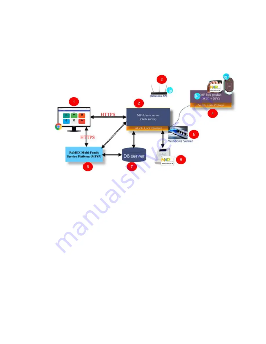
Figure 1 : Pamex Kapture System Architecture Overview
Figure 1 shows the system architecture of Pamex Kapture solution, Below are the brief
description of each components :
1. Chrome browser : The user interface to the MF-Admin Server (2). You need a PC
with Chrome browser to use MF-Admin. The card reader/writer (No.6 in figure 1) will
be connected to this PC using USB. You may also use the windows server (5) as the
client PC.
2. MF-Admin Server : An application running on Windows server (5). It provide all the
functions to manage the access control of the locks and the cards/fobs.
3. Wifi AP : All the Kapture locks has the wifi capability and are necessary to connect to
a wifi AP in order to be programmed by MF-Admin server. There should be a few to
many Wifi APs at a multi-family property. Wifi AP is not part of Kapture products.
Check the lock specifications in Appendix for the compatible Wifi AP.
4. Kapture smart locks and NFC cards : All the Kapture locks are smart locks which are
accessed using NFC card/fob (Mifare Desfire).
5. Windows Server : MF-Admin server is installed on this server.
6. Card Reader/Writer : MP100 is the default reader to issue new card/fob to
users/residents.
Summary of Contents for Kapture KA-WR1N
Page 10: ...9 Front View Figure 3 Kapture KA WR1S Front Kapture KA WR1N Front ...
Page 11: ...10 Back View Figure 4 Kapture KA WR1S Back Kapture KA WR1N Back ...
Page 13: ...12 Basic Door Installation Figure 6 Kapture KA WR1S N Basic Door Installation ...
Page 14: ...13 Basic Door Installation Wiring Figure 7 Kapture KA WR1S N Basic Door Installation Wiring ...
Page 15: ...14 Solid State Output Figure 8 Kapture KA WR1S N Solid State Output ...
Page 16: ...15 Surface Mounting Figure 9 Kapture KA WR1S N Surface Mounting ...
Page 18: ...17 Dimensions Figure 11 Kapture KA WR1S Front Figure 12 Kapture KA WR1N Front ...
Page 19: ...18 Back Figure 13 Kapture KA WR1S Back ...
Page 20: ...19 Figure 14 Kapture KA WR1N Back ...
Page 27: ...26 Product Photo Mark ...
Page 28: ...27 Dimensions 內外機 Mark ...
Page 29: ...28 Installation Guide ...
Page 32: ...31 Product Photo Mark ...
Page 33: ...32 Dimensions 內外機 Mark ...
Page 34: ...33 Installation Guide D1 Installation Guide ...
Page 37: ...36 Product Photo Mark ...
Page 38: ...37 Dimensions 內外機 Mark ...
Page 39: ...38 Installation Guide ...
Page 42: ...41 Product Photo Mark ...
Page 43: ...42 Installation Guide ...
Page 46: ...45 Product Photo Mark ...
Page 47: ...46 Installation Guide ...
Page 63: ...62 Place key card on reader first Click Read Key From Reader to get Key s UID ...
Page 81: ...80 Place key card on reader first Click Read Key From Reader to get Key s UID ...
Page 91: ...90 Check the box on Group Area M and click time control button to edit ...
Page 93: ...92 Click Issue Write Key to issue the vendor key Place key card on reader first ...
Page 99: ...98 Place key card on reader first Click Read Key From Reader to get Key s UID ...
Page 118: ...117 Factory default settings Deadbolt Same as Wall Reader ...
Page 119: ...118 Factory default settings Leverset Same as Wall Reader ...
Page 120: ...119 Factory default settings Interconnect Same as Wall Reader ...


