


110
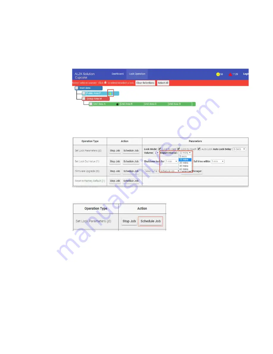
Click lock icon to select lockplace
Public Area P (
multiple selections allowed
here
)
, at
Set Lock Parameters (j0)
field find out
Report Interval
parameters
and set up it to
15 mins
.
Click
Schedule Job
to change the report interval setting.
To save the battery’s life, Pamex Kapture smart lock is not always connected to
MF-Admin Server. The lock will connect to the MF-Admin Server for every 1800 secs
by default. This also indicate one thing to bare in mind : every change to the card or
lock will sync to locks in 1800 secs at most. For example, when you issue a card at
9:00 am, the card number will be downloaded to the related physical lock(s) at next
reporting time which could be anytime before 9:30 am depending on the last report
time.
There is another way to force a lock to communicate with MF-Admin server
immediately. Four real time events (See Appendix) will cause a lock to communicate
with MF-Admin server. Therefore, when you want to make sure the lock to sync cards
or execute lock operation commands immediately without waiting for 30 mins, just
Summary of Contents for Kapture KA-WR1N
Page 10: ...9 Front View Figure 3 Kapture KA WR1S Front Kapture KA WR1N Front ...
Page 11: ...10 Back View Figure 4 Kapture KA WR1S Back Kapture KA WR1N Back ...
Page 13: ...12 Basic Door Installation Figure 6 Kapture KA WR1S N Basic Door Installation ...
Page 14: ...13 Basic Door Installation Wiring Figure 7 Kapture KA WR1S N Basic Door Installation Wiring ...
Page 15: ...14 Solid State Output Figure 8 Kapture KA WR1S N Solid State Output ...
Page 16: ...15 Surface Mounting Figure 9 Kapture KA WR1S N Surface Mounting ...
Page 18: ...17 Dimensions Figure 11 Kapture KA WR1S Front Figure 12 Kapture KA WR1N Front ...
Page 19: ...18 Back Figure 13 Kapture KA WR1S Back ...
Page 20: ...19 Figure 14 Kapture KA WR1N Back ...
Page 27: ...26 Product Photo Mark ...
Page 28: ...27 Dimensions 內外機 Mark ...
Page 29: ...28 Installation Guide ...
Page 32: ...31 Product Photo Mark ...
Page 33: ...32 Dimensions 內外機 Mark ...
Page 34: ...33 Installation Guide D1 Installation Guide ...
Page 37: ...36 Product Photo Mark ...
Page 38: ...37 Dimensions 內外機 Mark ...
Page 39: ...38 Installation Guide ...
Page 42: ...41 Product Photo Mark ...
Page 43: ...42 Installation Guide ...
Page 46: ...45 Product Photo Mark ...
Page 47: ...46 Installation Guide ...
Page 63: ...62 Place key card on reader first Click Read Key From Reader to get Key s UID ...
Page 81: ...80 Place key card on reader first Click Read Key From Reader to get Key s UID ...
Page 91: ...90 Check the box on Group Area M and click time control button to edit ...
Page 93: ...92 Click Issue Write Key to issue the vendor key Place key card on reader first ...
Page 99: ...98 Place key card on reader first Click Read Key From Reader to get Key s UID ...
Page 118: ...117 Factory default settings Deadbolt Same as Wall Reader ...
Page 119: ...118 Factory default settings Leverset Same as Wall Reader ...
Page 120: ...119 Factory default settings Interconnect Same as Wall Reader ...


