26
Chapter 2
Packard Bell ENTK36 BIOS
Information
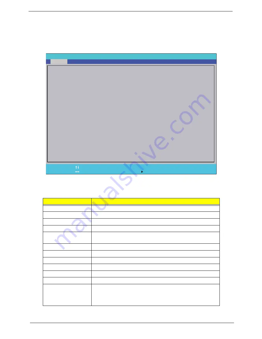
The Information screen displays a summary of the computer hardware information.
NOTE:
The screen above is for your reference only. Actual values may differ according to model.
The table below describes the parameters in this screen. Settings in
boldface
are the default and suggested
parameter settings
Parameter
Description
CPU Type
This field shows the CPU type and speed of the system.
CPU Speed
This field shows the speed of the CPU.
IDE0 Model Name
This field shows the model name of IDE0 installed on the system.
IDE0 Serial Number
This field displays the serial number of IDE0 installed on the system.
ATAPI Model Name
This field shows the model name of the Optical device installed in
the system.
System BIOS Version
Displays system BIOS version.
VGA BIOS Version
This field displays the VGA firmware version of the system.
Serial Number
This field displays the serial number of this unit.
Asset Tag Number
This field displays the asset tag number of the system.
Product Name
This field shows product name of the system.
Manufacturer Name
This field displays the manufacturer of this system.
UUID
Universally Unique Identifier (UUID) is an identifier standard used in
software construction, standardized by the Open Software
Foundation (OSF) as part of the Distributed Computing Environment
(DCE).
I n s y d e H 2 0 S e t u p U t i l i t y R e v . 3 . 5
F 1
E S C
H e l p
E x i t
S e l e c t I t e m
S e l e c t M e n u
C h a n g e Va l u e s
S e l e c t
S u b M e n u
E n t e r
F 9
F 1 0
S e t u p D e f a u l t
S a v e a n d E x i t
I n t e l ( R ) C e l e r o n ( R ) C P U 9 0 0 @ 2 . 2 0 G H z
2 . 2 0 G H z
H i t a c h i H T S 5 4 5 0 3 2 B 9 A 3 0 0
1 0 0 6 1 0 P B 5 3 0 4 D 6 G P D R R G
H L - D T - S T D V D R A M G T 3 2 N
V 0 . 0 5 T 1
I n t e l V 1 8 0 0
4 5 D B 7 C 2 D - 1 6 4 4 - 1 1 D F - 9 5 8 C - 8 8 A E 1 D 6 2 8 1 6 2
C P U T y p e :
C P U S p e e d :
I D E O M o d e l N a m e :
I D E O S e r i a l N u m b e r :
A T A P I M o d e l N a m e :
S y s t e m B I O S V e r s i o n :
V G A B I O S V e r s i o n :
S e r i a l N u m b e r
A s s e t T a g N u m b e r :
P r o d u c t N a m e :
M a n u f a c t u r e r N a m e :
U U I D :
F 5 / F 6
Main
Boot
Exit
Security
Information
Summary of Contents for ENTK36 Series
Page 6: ...VI ...
Page 10: ...X Table of Contents ...
Page 66: ...56 Chapter 3 4 Detach the WLAN module from the WLAN socket ...
Page 76: ...66 Chapter 3 5 Lift the speaker module clear of the device ...
Page 87: ...Chapter 3 77 10 Disconnect the Bluetooth cable from mainboard ...
Page 92: ...82 Chapter 3 8 Remove the LCD assembly from the lower cover ...
Page 103: ...Chapter 3 93 5 Lift the microphone set clear of the panel ...
Page 114: ...104 Chapter 3 4 Replace the adhesive tape securing the inverter board cable to the LCD cover ...
Page 120: ...110 Chapter 3 7 Replace the adhesive tape to secure the antennas to the lower cover ...
Page 123: ...Chapter 3 113 5 Connect the fan cable ...
Page 130: ...120 Chapter 3 4 Connect the USB cable to the mainboard and lock the connector ...
Page 134: ...124 Chapter 3 Replacing the Upper Cover 1 Place the upper cover on the lower cover as shown ...
Page 136: ...126 Chapter 3 4 Connect the speaker cable B 5 Connect and lock the touchpad FFC C ...
Page 138: ...128 Chapter 3 Replacing the RTC Battery 1 Place the RTC battery into the mainboard connector ...
Page 140: ...130 Chapter 3 4 Slide the HDD module in the direction of the arrow to connect the interface ...
Page 198: ...Appendix A 188 ...
Page 206: ...196 Appendix C ...
Page 210: ...200 ...


