Communication
GTW/EN
CT/C40
PACiS Gateway
Page 49/64
7. OPC
PROTOCOL
7.1 Implementation
All required OPC Interfaces are supported for both OPC 1.0 and OPC 2.0 Data Access
Standards as well as the Browse Interface (
OPC DA 2.05
).
The OPC Protocol basically operates as a data librarian. The controlling application creates
Process Tags by passing a name and value to the DLL. The DLL records the data point and
makes it available to any OPC Client application by name. The controlling application may
change the value of the data at any time, and all attached clients would be automatically
notified. Callback notification is provided for any Process Tag that is modified by an OPC
Client connection. (The application has control over which tags are OPC_WRITEABLE only
for control datapoints.)
Registration
The Opc Server registration is made by the gateway installation sofware if you choiced OPC
Protocol.
Two arguments are needed for this phase: CLSID and PROGID
CLSID: {8087E613-3ED9-11D7-827E-00E029555839}
PROGID: Schneider Electric.OPC SERVER.V2.0
Initialization
When this phase is executed, the DLL performs all necessary initialization of COM/DCOM
and creates the OPCServer Interface object to be used for client connections. The specified
ServerRate defines how fast the OPC Client data connections are refreshed (ServerRate is
configured in registry)
Creating Process Tags
As each process tag is created, the DLL returns a HANDLE to identify the point for future
references, (updates), from the application. The naming convention used for browsing
operations, (OPC_NS_FLAT or OPC_NS_HIERARCHIAL), is a function of how the names
are assigned by the controlling application. If segmented names are used to create the tags,
(strings containing the delimiter ‘.’), the DLL will automatically configure the name space as
hierarchial, otherwise a flat name space is used. The names are configured by PACiS SCE.
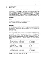
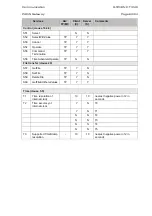
Each process tag is configured with a type which identifiy the type of Variant used for
update.
Type of datapoint
Type of TAG configurable
Type of VARIANT used
SPS (single point status)
BOOL,BYTE
VT_BOOL,VT_UI1
DPS (double point status)
BOOL,BYTE
VT_BOOL,VT_UI1
MPS (multiple point status)
BYTE,WORD
VT_UI1,VT_UI2
MV (measurement)
FLOAT
VT_R4
TPI (Tap changer indicator)
WORD
VT_I2
Counter DWORD VT_I4
SPC (single point control)
BOOL,BYTE
VT_BOOL,VT_UI1
DPC (double point control)
BOOL,BYTE
VT_BOOL,VT_UI1
Setpoint FLOAT VT_R4
Only SPC,DPC and Setpoint are OPC_WRITABLE tags.
Summary of Contents for GTW/EN T/C40
Page 1: ...PACiS GTW Gateway GTW EN T C40 Version 4 5 Technical Guide ...
Page 2: ......
Page 4: ...GTW EN T C40 Technical Guide Page 2 2 PACiS GTW gateway BLANK PAGE ...
Page 5: ...Safety Handling GTW EN SA C40 PACiS GTW gateway SAFETY HANDLING ...
Page 6: ......
Page 8: ...GTW EN SA C40 Safety Handling Page 2 8 PACiS GTW gateway BLANK PAGE ...
Page 14: ...GTW EN SA C40 Safety Handling Page 8 8 PACiS GTW gateway BLANK PAGE ...
Page 15: ...Technical Data GTW EN TD C40 PACiS GTW gateway TECHNICAL DATA ...
Page 16: ......
Page 31: ...Introduction GTW EN IT C40 PACiS GTW Gateway INTRODUCTION ...
Page 32: ......
Page 34: ...GTW EN IT C40 Introduction Page 2 8 PACiS GTW Gateway BLANK PAGE ...
Page 40: ...GTW EN IT C40 Introduction Page 8 8 PACiS GTW Gateway BLANK PAGE ...
Page 41: ...Hardware Description GTW EN HW C40 PACiS GTW gateway HARDWARE DESCRIPTION ...
Page 42: ......
Page 44: ...GTW EN HW C40 Hardware Description Page 2 8 PACiS GTW gateway BLANK PAGE ...
Page 51: ...Connection GTW EN CO C40 PACiS Gateway CONNECTION ...
Page 52: ......
Page 54: ...GTW EN CO C40 Connection Page 2 8 PACiS Gateway BLANK PAGE ...
Page 60: ...GTW EN CO C40 Connection Page 8 8 PACiS Gateway BLANK PAGE ...
Page 61: ...Installation GTW EN IN C40 PACiS Gateway INSTALLATION ...
Page 62: ......
Page 64: ...GTW EN IN C40 Installation Page 2 30 PACiS Gateway BLANK PAGE ...
Page 82: ...GTW EN IN C40 Installation Page 20 30 PACiS Gateway Don t forget to click on the Apply button ...
Page 93: ...Human Interface GTW EN HI C40 PACiS GTW gateway HUMAN INTERFACE ...
Page 94: ......
Page 96: ...GTW EN HI C40 Human Interface Page 2 12 PACiS GTW gateway BLANK PAGE ...
Page 106: ...GTW EN HI C40 Human Interface Page 12 12 PACiS GTW gateway BLANK PAGE ...
Page 107: ...Communication GTW EN CT C40 PACiS Gateway COMMUNICATION ...
Page 108: ......
Page 172: ...GTW EN CT C40 Communication Page 64 64 PACiS Gateway BLANK PAGE ...
Page 173: ...Commissioning GTW EN CM C40 PACiS GTW gateway COMMISSIONING ...
Page 174: ......
Page 176: ...GTW EN CM C40 Commissioning Page 2 4 PACiS GTW gateway BLANK PAGE ...
Page 179: ...Record Sheet GTW EN RS C40 PACiS GTW gateway RECORD SHEET ...
Page 180: ......
Page 182: ...GTW EN RS C40 Record Sheet Page 2 6 PACiS GTW gateway BLANK PAGE ...
Page 187: ...Maintenance GTW EN MF C40 PACiS GTW gateway MAINTENANCE ...
Page 188: ......
Page 192: ...GTW EN MF C40 Maintenance Page 4 68 PACiS GTW gateway BLANK PAGE ...
Page 256: ...GTW EN MF C40 Maintenance Page 68 68 PACiS GTW gateway BLANK PAGE ...
Page 257: ...Problem Analysis GTW EN PR C40 PACiS GTW gateway PROBLEM ANALYSIS ...
Page 258: ......
Page 260: ...GTW EN PR C40 Problem Analysis Page 2 4 PACiS GTW gateway BLANK PAGE ...
Page 263: ...Functional Description GTW EN FT C40 PACiS Gateway FUNCTIONAL DESCRIPTION ...
Page 264: ......
Page 266: ...GTW EN FT C40 Functional Description Page 2 12 PACiS GTW gateway BLANK PAGE ...
Page 276: ...GTW EN FT C40 Functional Description Page 12 12 PACiS GTW gateway BLANK PAGE ...
Page 277: ...Logical Diagram GTW EN LG C40 PACiS GTW gateway LOGICAL DIAGRAM ...
Page 278: ......
Page 280: ...GTW EN LG C40 Logical Diagram Page 2 6 PACiS GTW gateway BLANK PAGE ...
Page 284: ...GTW EN LG C40 Logical Diagram Page 6 6 PACiS GTW gateway BLANK PAGE ...
Page 285: ...Glossary GTW EN LX C40 PACiS GTW gateway GLOSSARY ...
Page 286: ......
Page 287: ...Glossary GTW EN LX C40 PACiS GTW gateway Page 1 10 CONTENT 1 INTRODUCTION 3 2 LEXICAL 4 ...
Page 288: ...GTW EN LX C40 Glossary Page 2 10 PACiS GTW gateway BLANK PAGE ...
Page 297: ......

