Communication
GTW/EN
CT/C40
PACiS Gateway
Page 7/64
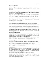
Controlled station failure
If its register key
Send_init_asdu_70
is set to 1 the controlled station shall indicate to the
controlling station that it has initialised by sending a frame indicating End of Initialisation
(ASDU 70) with a Cause of Initialisation (COI) field, which will identify the reason for the
initialisation.
Data Acquisition by Polling
The default for all analogue values shall be reporting as Class 2 data (COT=1, periodic,
cyclic, or COT = 2, BackgroundScan cyclic).
Values returned as Class 2 data do not have a time tag (since they are constantly repeated).
The controlled station may return Class 1 data in response to a Class 2 request if no Class 2
data is available and Class 1 data is awaiting transmission. This is configurable in Registry.
At the controlled station, if a request for Class 2 data is received and no data is available a
negative response, data not available, shall be returned to the controlling Station. The
negative response may be a fixed length frame (FC=9) or the Single Control Character (E5),
which in this case is treated as a NACK.
Normal Acquisition of Events
The default for all status changes are reported as Class 1 data (COT=3, spontaneous).
Values returned as Class 1 data shall have a time tag (either CP24Time2a, or CP56Time2a).
Status changes at the controlled station shall cause the ACD bit to be set in the next Class 1
or Class 2 data response. The controlling station shall respond to ACD set by inserting a
scan for Class 1 (spontaneous) data as the next scan.
The response to a Class 1 data request shall also have the ACD bit set if more Class 1 data
is awaiting transmission. In this case a further scan for Class 1 data shall be scheduled by
the controlling station.
Abnormal Acquisition of Events
At the controlled station, if a request for Class 1 data is received and no data is available an
error should be raised and a negative response, data not available, returned to the
controlling Station. The negative response shall be a fixed length frame (FC=9) or the single
Control Character (E5), which in this case is treated as a NACK.
At the controlling station, if a response to a scan for Class 1 data indicates no data is
available an error shall be raised and scanning returned to Class 2 data requests.
General Interrogation
The GI returns the current status information directly from the Controlled station database.
If register key
timetag_in_GI
is set to 0 time tags are not used for data items returned as
part of the GI response. if this register key is set to 1 DI and AI are time-tagged.
The GI groups are supported so, these will be set up in the database and each of the (up to
16) groups shall be requested/reported individually.
Synchronisation
Class 1 data can be time-tagged with the 3 bytes time-stamp (CP24Time2a), giving minutes
and milliseconds within the hour, or with the 7 bytes time-stamp (CP56Time2a), giving
minutes and milliseconds within the hours, day, month, year. The format of time-stamp can
be defined, for all class1 data, in configuration.
The invalid bit in the time-stamp is set when the time source is not available.
If its register key
Inhibition_Clock_Synchro
is set to 0 the controlled station reports its change
of hour by sending a clock synchronisation message (ASDU 103) to the controlling station,
as Class 1 data, with a cause of transmission spontaneous (3). If this register key is set to 1
no clock synchronisation message is sent.
Summary of Contents for GTW/EN T/C40
Page 1: ...PACiS GTW Gateway GTW EN T C40 Version 4 5 Technical Guide ...
Page 2: ......
Page 4: ...GTW EN T C40 Technical Guide Page 2 2 PACiS GTW gateway BLANK PAGE ...
Page 5: ...Safety Handling GTW EN SA C40 PACiS GTW gateway SAFETY HANDLING ...
Page 6: ......
Page 8: ...GTW EN SA C40 Safety Handling Page 2 8 PACiS GTW gateway BLANK PAGE ...
Page 14: ...GTW EN SA C40 Safety Handling Page 8 8 PACiS GTW gateway BLANK PAGE ...
Page 15: ...Technical Data GTW EN TD C40 PACiS GTW gateway TECHNICAL DATA ...
Page 16: ......
Page 31: ...Introduction GTW EN IT C40 PACiS GTW Gateway INTRODUCTION ...
Page 32: ......
Page 34: ...GTW EN IT C40 Introduction Page 2 8 PACiS GTW Gateway BLANK PAGE ...
Page 40: ...GTW EN IT C40 Introduction Page 8 8 PACiS GTW Gateway BLANK PAGE ...
Page 41: ...Hardware Description GTW EN HW C40 PACiS GTW gateway HARDWARE DESCRIPTION ...
Page 42: ......
Page 44: ...GTW EN HW C40 Hardware Description Page 2 8 PACiS GTW gateway BLANK PAGE ...
Page 51: ...Connection GTW EN CO C40 PACiS Gateway CONNECTION ...
Page 52: ......
Page 54: ...GTW EN CO C40 Connection Page 2 8 PACiS Gateway BLANK PAGE ...
Page 60: ...GTW EN CO C40 Connection Page 8 8 PACiS Gateway BLANK PAGE ...
Page 61: ...Installation GTW EN IN C40 PACiS Gateway INSTALLATION ...
Page 62: ......
Page 64: ...GTW EN IN C40 Installation Page 2 30 PACiS Gateway BLANK PAGE ...
Page 82: ...GTW EN IN C40 Installation Page 20 30 PACiS Gateway Don t forget to click on the Apply button ...
Page 93: ...Human Interface GTW EN HI C40 PACiS GTW gateway HUMAN INTERFACE ...
Page 94: ......
Page 96: ...GTW EN HI C40 Human Interface Page 2 12 PACiS GTW gateway BLANK PAGE ...
Page 106: ...GTW EN HI C40 Human Interface Page 12 12 PACiS GTW gateway BLANK PAGE ...
Page 107: ...Communication GTW EN CT C40 PACiS Gateway COMMUNICATION ...
Page 108: ......
Page 172: ...GTW EN CT C40 Communication Page 64 64 PACiS Gateway BLANK PAGE ...
Page 173: ...Commissioning GTW EN CM C40 PACiS GTW gateway COMMISSIONING ...
Page 174: ......
Page 176: ...GTW EN CM C40 Commissioning Page 2 4 PACiS GTW gateway BLANK PAGE ...
Page 179: ...Record Sheet GTW EN RS C40 PACiS GTW gateway RECORD SHEET ...
Page 180: ......
Page 182: ...GTW EN RS C40 Record Sheet Page 2 6 PACiS GTW gateway BLANK PAGE ...
Page 187: ...Maintenance GTW EN MF C40 PACiS GTW gateway MAINTENANCE ...
Page 188: ......
Page 192: ...GTW EN MF C40 Maintenance Page 4 68 PACiS GTW gateway BLANK PAGE ...
Page 256: ...GTW EN MF C40 Maintenance Page 68 68 PACiS GTW gateway BLANK PAGE ...
Page 257: ...Problem Analysis GTW EN PR C40 PACiS GTW gateway PROBLEM ANALYSIS ...
Page 258: ......
Page 260: ...GTW EN PR C40 Problem Analysis Page 2 4 PACiS GTW gateway BLANK PAGE ...
Page 263: ...Functional Description GTW EN FT C40 PACiS Gateway FUNCTIONAL DESCRIPTION ...
Page 264: ......
Page 266: ...GTW EN FT C40 Functional Description Page 2 12 PACiS GTW gateway BLANK PAGE ...
Page 276: ...GTW EN FT C40 Functional Description Page 12 12 PACiS GTW gateway BLANK PAGE ...
Page 277: ...Logical Diagram GTW EN LG C40 PACiS GTW gateway LOGICAL DIAGRAM ...
Page 278: ......
Page 280: ...GTW EN LG C40 Logical Diagram Page 2 6 PACiS GTW gateway BLANK PAGE ...
Page 284: ...GTW EN LG C40 Logical Diagram Page 6 6 PACiS GTW gateway BLANK PAGE ...
Page 285: ...Glossary GTW EN LX C40 PACiS GTW gateway GLOSSARY ...
Page 286: ......
Page 287: ...Glossary GTW EN LX C40 PACiS GTW gateway Page 1 10 CONTENT 1 INTRODUCTION 3 2 LEXICAL 4 ...
Page 288: ...GTW EN LX C40 Glossary Page 2 10 PACiS GTW gateway BLANK PAGE ...
Page 297: ......

