SECTION 6
SERVICE
Pacific Power Source ©2013
6-36
Document # 126050-10 Rev E
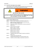
6.5.1 INVERTER ASSEMBLY REPLACEMENT
This procedure is to be used to replace an MS-Series Inverter Assembly. Input
power MUST be removed before attempting this procedure.
Inverter Assembly Replacement
STEP 1:
Remove input power.
STEP 2:
Remove front covers and sub panels.
STEP 3
Verify the red LEDs on the discharge PCB are off. With a DC
voltmeter verify less than 5 VDC from each Bus bar to chassis.
STEP 4:
Remove five screws from the top of the keyboard sub panel.
Fold down the keyboard sub panel.
Disconnect ribbon cables from Modulator PCB.
STEP 5:
Remove Bus bars from the front of the inverters. Be careful not
to spin the studs.
Disconnect P33, the fan wires and push them up into the control
box.
Remove three screws at the bottom of the Inverter assembly.
Slide Inverter assembly out of mainframe.
STEP 6:
Slide Inverter assembly into mainframe.
Reinstall three screws at the bottom of the Inverter assembly.
STEP 7:
Replace Bus bars on the front of the inverters. Align all the holes
and bus bars prior to tightening. Be careful not to spin the studs.
Reconnect P33, the fan wires.
STEP 8:
Reconnect ribbon cables from Modulator PCB.
Fold up the keyboard sub panel.
Replace five screws from the top of the keyboard sub panel.
STEP 9:
Replace fuses, F10 and F11 if needed.
STEP 10: Replace sub panels and front covers.
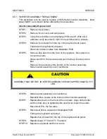
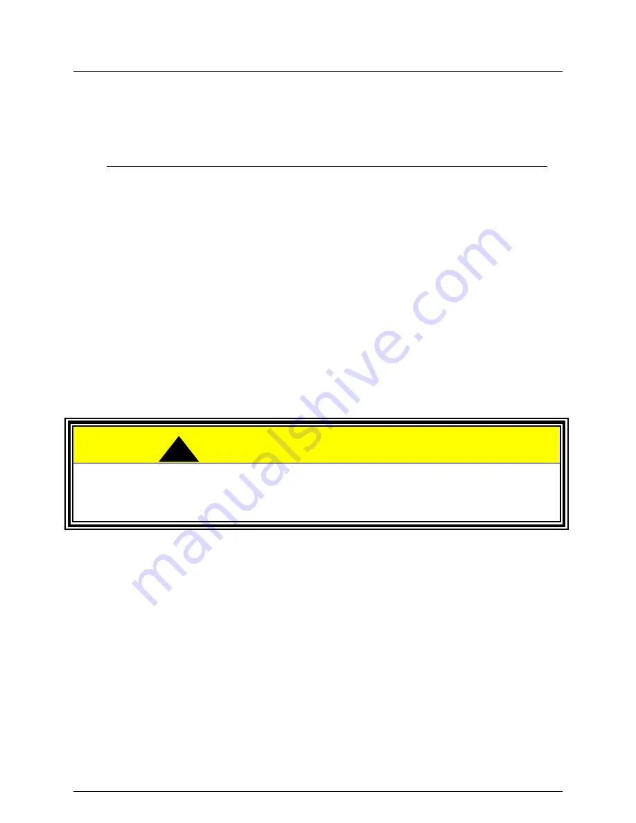
CAUTION
-
ASSEMBLY MAY BE HOT. INVERTER ASSEMBLY WEIGHS APPROXIMATELY 75
LBS.
!

