SECTION 6
SERVICE
Pacific Power Source ©2013
6-30
Document # 126050-10 Rev E
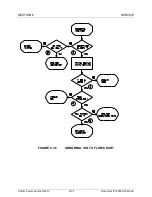
6.3.6 ABNORMAL VOLTAGE SERVICE PROCEDURE
This troubleshooting procedure should be used to locate a problem within the
Inverter circuits of the MS power source. Directions are given which locate a
fault to the PCB level or component level as appropriate. Do not use this
procedure unless instructed to do so by the performance check flow chart.
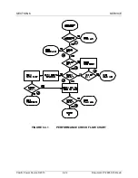
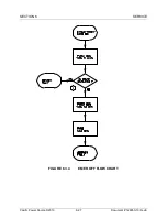
The numbered comments below correspond to the circled numbers on figure
6.3.6 and provide detailed instructions relative to the referenced step.
1.
If the Output Contactor, S5, is open, try to close it. Rotate the MODE
SELECT to ON and press START RESET. This should cause the Output
Contactor, S5, to close.
2.
If the Output Contactor, S5, is not closed, check for 115 VAC on the coil.
If 115 VAC is present on the coil and the contactor does not close replace
the contactor. If no voltage is present on the coil and the ON lamp is on,
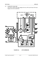
check the wiring or replace control PCB. Reference figure 6.4.1 LVPS
Schematic.
3.
Pressing the OUTPUT then f2 KEYS displays the system load in
percentages: %I-PEAK, %kVA and %kW. Verify that the machine is not
overloaded, (all six fields are less than 100%). If any field is greater than
100% the machine is overloaded; reduce the load.
4.
If voltage regulation is a problem, verify that the AGC is enabled. Switch
S14-6, S14-7 and S14-8 ON. Switch S14-3, S14-4 and S14-5 OFF.
Reference section 4.5.2.
5.
If all three phases have the same problem replace the Modulator PCB. If
only one phase has a problem swap two of the Inverters and see if the
problem follows the Inverter. If the problem follows the Inverter replace
that Inverter. If the problem stays on the same phase replace the
Modulator PCB.

