SECTION 6
SERVICE
Pacific Power Source ©2013
6-15
Document # 126050-10 Rev E
6.2.3 THEORY OF OPERATION - DC POWER SUPPLY
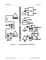
The low voltage power supply transformer, T2, generates 3 phase 16/28 VAC for
the low voltage DC power supplies and 3 phase 115 VAC for fans and contactor
coils. The LVPS PCB generates a regulated ±18 VDC from the 16/28 VAC. The
Control PCB continuously monitors the ±18 VDC Low Voltage DC supplies. If
any of these become abnormal, logic circuits on the Control PCB will initiate
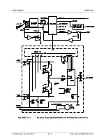
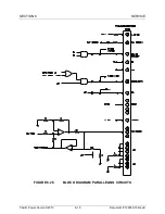
system shutdown. Refer to Figure 6.2.3 for the block diagram of this circuit.
The main input power transformer, T1, and power supply panel assembly, which
contains the rectifiers, capacitors and DC fuses, make up the main DC Power
Supply Circuits. The main DC Power Supply is a bipolar supply which produces
±200 VDC. This supply is an unregulated supply. It is actually two independent
200 VDC supplies which are stacked on top of each other. The rectifiers are
configured as two, full-wave three-phase bridges. These two bridges are
connected as shown and feed the capacitor assembly. The capacitors filter the
bridge outputs and DC is produced. The common point of this supply is Output
Neutral and is connected to the chassis. Two red LEDs, one for positive and one
for negative, on the Discharge PCB indicate BUS voltages are present.
The Control PCB continuously monitors the ±200 VDC and will shut down the
system if the DC is higher than 240 VDC or lower than 160 VDC.


