66251700-EN - V1.1 - 31/10/16
1
Accessories
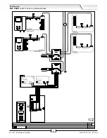
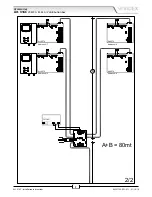
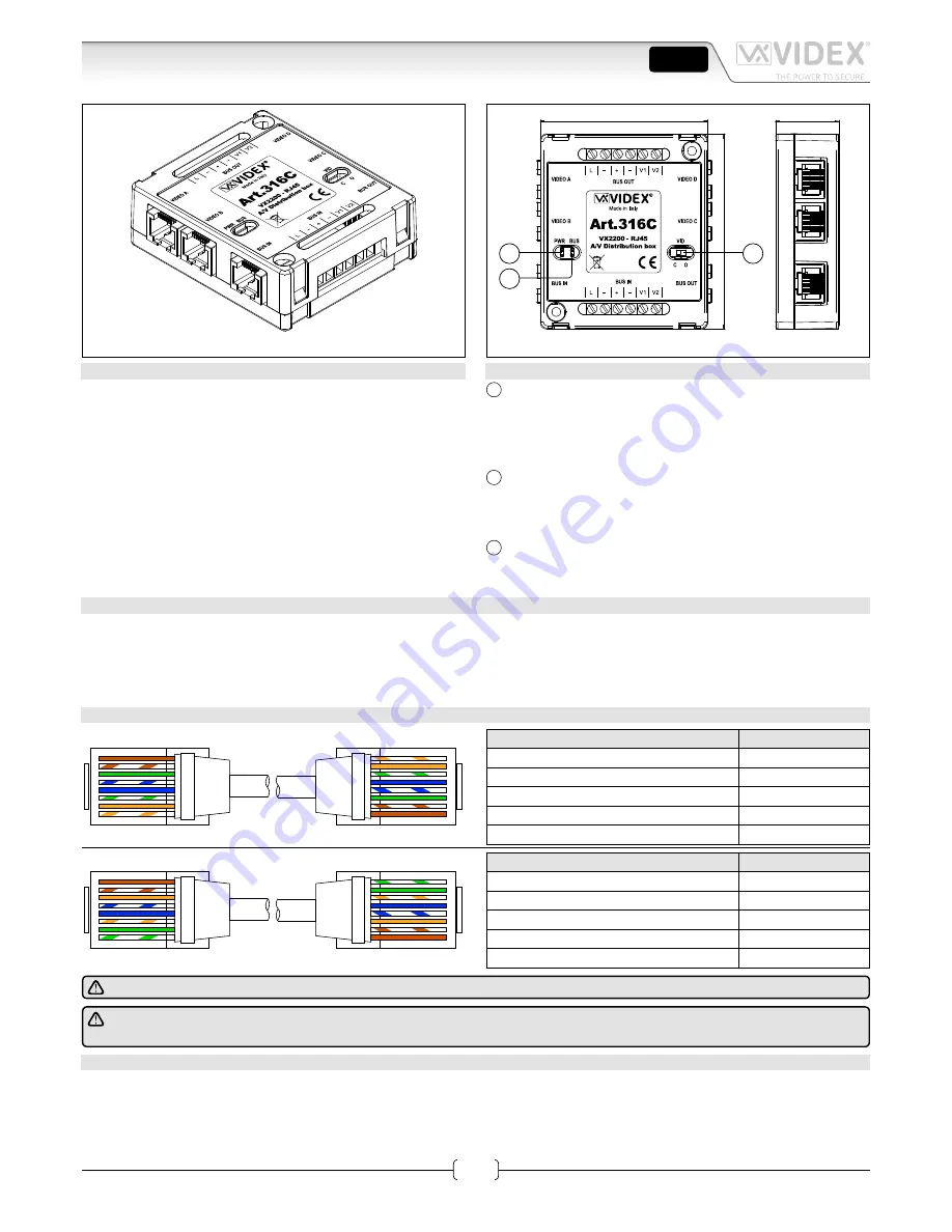
Art. 316C - Installation instructions
Art. 316C
VX2200 - RJ-45 A/V distribution box
Fig. 1
66
77
25
C
A
B
Fig. 2
DESCRIPTION
Due to the popularity of CAT5 cable for use on video intercom sys-
tem Videx have developed the Art. 316C, a 4 way distribution box
with RJ-45 connections for the VX2200 6 wire bus video system.
It distributes the power (+ & –), the bus (L & –) and the video
(V1 & V2) from the main bus to 4 apartment outputs with RJ-45
connector.
The distributor also include an in and an out connection to con-
nect multiple Art. 316C devices on the same bus.
The main bus connections include both RJ-45 and terminal con-
nections should a larger cable be required for the main bus en-
abling distanced of up to 400m.
LEGEND
A
Power LED.
When off this indicates there is no voltage between the ter-
minals “+” (plus) and “–” (minus).
Check that the wires are not interrupted or that the +20Vdc
power supply unit is connected to mains.
B
BUS LED.
When off this indicates there is no bus voltage which could
be he result of a short, a broken wire or if there is no master
door panel or concierge connected.
C
Video line termination switch.
End of line termination for the video. This should be set to “C”
(Closed) on the end of line device only.
KEY FEATURES
• Allows the installer to use standard CAT5 cable crimped to an RJ-45 plug
• 1 input / 1 output RJ-45 connection or standard 6 wire screw terminals
• 4 RJ-45 outputs to connect directly to 6000 Series monitors
• 1 switch to terminate the impedance of the video signal (End of Line)
• 2 fault diagnostic LED’s to indicate bus and power.
MATCHING SIGNALS OVER CAT5
EIA/TIA-568B
1
2
3
4
5
6
7
8
o
O
g
B
b
O
br
BR
8
7
6
5
4
3
2
1
BR
br
G
b
B
g
O
o
EIA/TIA-568B
RJ-45 pin
VX2200 Signal
1
and
2 (white-orange / orange)
L
3
and
4 (white-green / blue)
–
5
and
6 (white-blue / green)
+
7 (white-brown)
V1
8 (brown)
V2
EIA/TIA-568A
1
2
3
4
5
6
7
8
g
G
o
B
b
O
br
BR
8
7
6
5
4
3
2
1
BR
br
O
b
B
o
G
g
EIA/TIA-568A
RJ-45 pin
VX2200 Signal
1
and
2 (white-green / green)
L
3
and
4 (white-orange / blue)
–
5
and
6 (white-blue / orange)
+
7 (white-brown)
V1
8 (brown)
V2
NOTE: DO NOT USE CROSS OVER CABLES.
IMPORTANT NOTE: SOLID COPPER CABLES MUST BE USED. COPPER COATED STEEL (CCS) AND COPPER COATED
ALUMINIUM (CCA) CAN NOT BE USED ON THE SYSTEM.
TECHNICAL SPECIFICATION
Housing/Mounting:
ABS plastic box / surface mount
Power Supply:
20V dc
Power consumption:
Stand-by: 8mA
Max: 40mA
Working Temperature:
-10 +50 °C
ENG


