9
Fig. # 8
MAXIMUM
f i r e - p a r t s . c o m
Page 1: ...s supplier s instructions If you cannot reach your gas supplier call the fire department Installation and service must be performed by a qualified installer service agency or the gas supplier IMPORTAN...
Page 2: ...ALL INSTALLATION 7 CORNER INSTALLATION 8 BASEMENT INSTALLATION 10 ATTACHMENT TO FLOOR 10 ALTERNATE VENTING 11 VENT TERMINAL INSTALLATION 15 GLASS FRONT REMOVAL 16 LOG SET 17 GLOWING EMBERS 17 FIRST FI...
Page 3: ...ved cracked or broken Replacement of glass should be done by a licensed or qualified service person Do not strike or otherwise impact the glass in anyway that may cause ittobreak Iftheglassbecomescrac...
Page 4: ...ttom of the control assembly 5 Connect burner switch wires to the back of the rocker switch 6 Insert valve knob extensions through the control panel and onto their corresponding valve knobs Fig 2 7 In...
Page 5: ...ired Alcove sidewall to appliance clearance is listed at 4 3 4 A 10 clearance is recommended to center the appliance in a 48 minimum wide Alcove Sidewall to Appliance 3 in 76 mm Rearwall to Appliance...
Page 6: ...ON PRECAUTIONS The Oxford Heater installation and venting must conform with local codes or in the absence of local codes with the current Canadian Installation Code CAN CGA B149 in Canada or the curre...
Page 7: ...ll thickness and or rear clearance of the stove Measure the wall thickness from the finished trim collar surface to the exterior mounting surface for the vent terminal Add 1 4 inch plus rear clearance...
Page 8: ...6 Attach the coaxial 45 elbow LB 45 to the unit Slide the 5 inch inner elbow pipe 1 inch over top of the collar and secure with three sheet metal screws Seal the joint with high temperature silicone N...
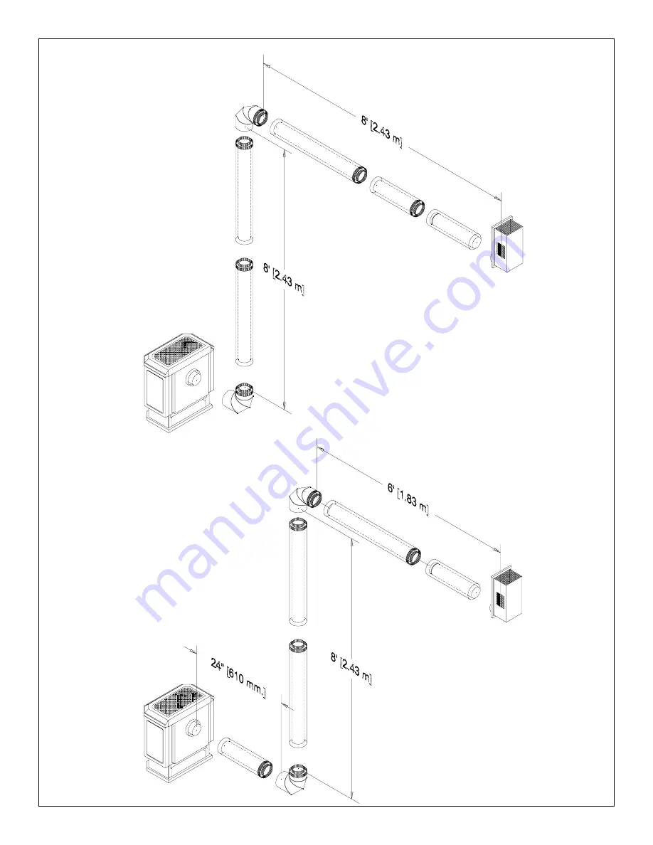
Page 9: ...9 Fig 8 MAXIMUM MAXIMUM MAXIMUM MAXIMUM MAXIMUM fire parts com...
Page 10: ...gh temperature silicone and secured with screws 3 Continue adding vent components per the pre planned system configuration Support spacer must be used for each 6 feet of vertical and horizontal run Th...
Page 11: ...are main tained Follow vent pipe manufacturer s instructions for assembly and installation ALTERNATE VENTING SIMPSON DURA VENT DIRECT VENT GS SYSTEM CAUTION UNDER NO CONDITION SHOULD COMBUSTIBLE MATER...
Page 12: ...nimum 6 vertical rise is required for a wall termination see Fig 9a For horizontal runs greater than 6 increase vertical rise equally Horizontal run must not exceed 8 feet Any combination of rise grea...
Page 13: ...to 30 feet is permited with no horizontal run If horizontal run is required ensure that vertical rise is equal or greater than run Horizontal run must not exceed 8 feet Combined vent length must not e...
Page 14: ...on Cap Vertical 991 Low Profile Termination Cap Vertical 980 Extended Vertical Termination Cap Vertical 930 Horizontal Square Termination Cap 984 Snorkel Termination Cap 36 981 Snorkel Termination Cap...
Page 15: ...rom the center line of the terminal 18 inches 46 cm minimum E clearance to unventilated soffit 18 inches 46 cm minimum F clearance to outside corner 8 inches 20 cm minimum G clearance to inside corner...
Page 16: ...damage Handle enamelled parts carefully to avoid chipping Window Frame Removal 1 Remove two wing nuts located at the base of the window frame 2 Grasp the sides of the frame and swing the bottom out t...
Page 17: ...y are very fragile Note Improper placement of logs may cause soot ing on internal parts and glass Step 2 Left Log Placement log 2 Step 3 Right Log Placement log 3 Step 4 Middle Twig Placement log 4 St...
Page 18: ...n gas valve knob clockwise past Pilot to Off position Note Knob cannot be turned from Pilot to Off unless knob is pushed in slightly Do not force 5 Wait five 5 minutes to clear out any gas Then smell...
Page 19: ...a comfortable temperature Turn the HI LO burner control knob to a desired setting As heat is required the Oxford heater will turn on or off automatically as needed Extend Shutdown To shutdown the appl...
Page 20: ...SC THERMO OPTIONAL WALL SWITCH OPTIONAL REMOTE CONTROL GASC REMOTE ROCKER SWITCH THERMOPILE GAS VALVE Fig 18 Recommended Thermostat Wire Size Wire Size Max Length 14 ga 100 ft 16 ga 60 ft 18 ga 40 ft...
Page 21: ...AL BASE OXFD 2546 16 FRONT OVERLAY OXFD 2599_ _ 17 WINDOW FRAME OXFD 2518 18 GLASS GASKET KIT MFSD 50671 19 REPLACEMENT GLASS 5034 1 20 FRONT FIREBOX PANEL 5097 661 21 LEFT FIREBOX PANEL 5097 662 22 R...
Page 22: ...22 NOTES fire parts com...
Page 23: ...01A in the U S A Cet appareil diot tre install conformem nt aux exigences de la norme CAN CSA Z240 MH en vigueur de l ACNOR Installations de gaz dans les Constructions Mobiles This appliance is only f...
Page 24: ...24 Pacific Energy Fireplace Products Ltd PO Box 1060 Duncan B C V9L 3Y2 Phone 250 748 1184 Web site http www pacificenergy net Printed in Canada fire parts com...