System Operations Manual
www.paceworldwide.com
Page 13 of 50
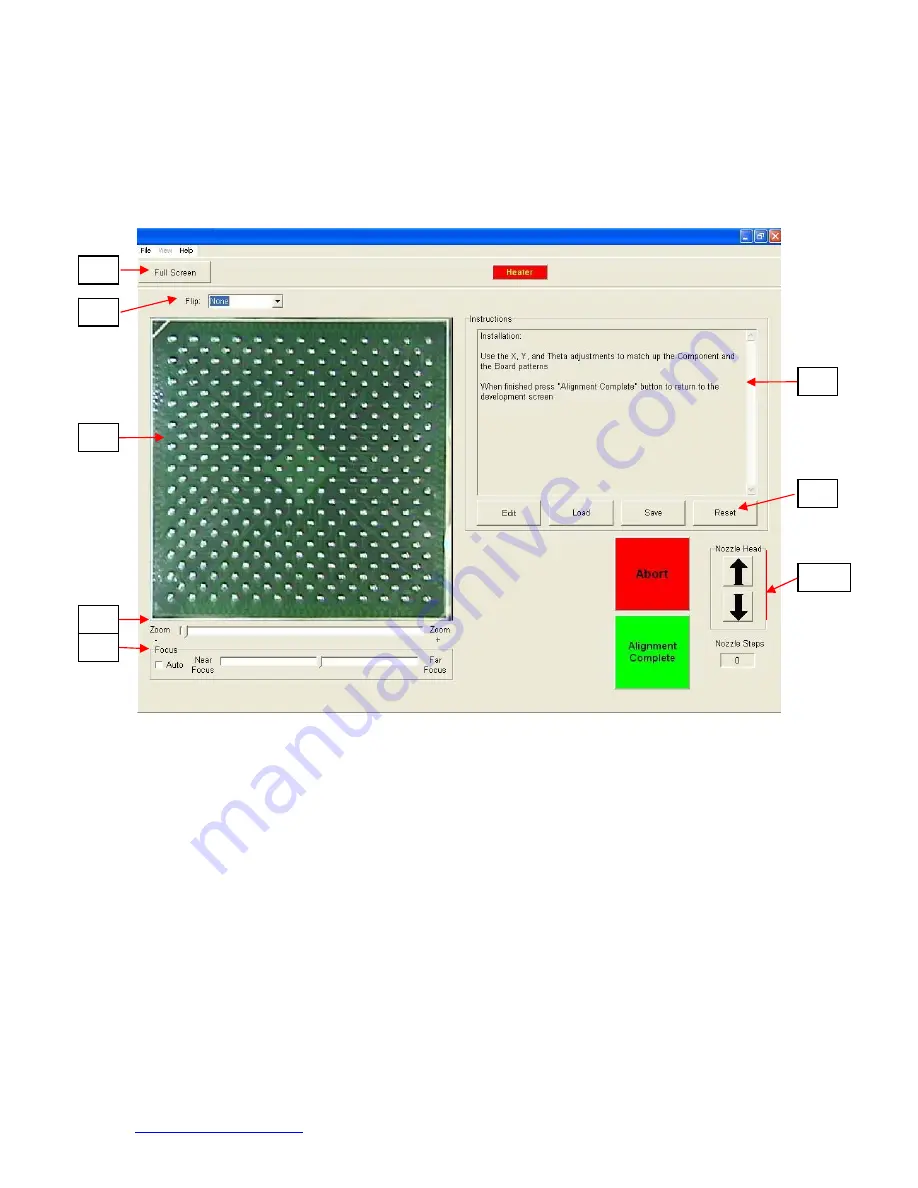
b. Alignment Screen Features (Figure 5)
Figure 5
i. Full Screen. Click on here to view image full screen.
ii. Flip Image. Allows operator to flip the image horizontally or vertically.
iii. Component/PCB alignment image. Proper alignment is viewed here showing
the PCB pads directly under the component pads.
iv. Zoom bar. The image can be zoomed in or out using this bar.
v. Focus bar. The image can be manually focused using the slider on this bar or
it can be automatically focused by checking the box by “auto.”
vi. Instructions. Follow these instructions to proceed through the alignment
sequence.
vii. Modify Instructions.
1. Edit – Change current profile instructions.
2. Load – Loads saved profile.
3. Save – Saves changes made to instructions.
4. Reset – Returns to factory set instructions.
viii. Nozzle step adjustment. If component cannot be aligned nozzle height up or
down with this option until better alignment or focus is achieved.
iii
iv
v
vi
vi
viii
ii
i


