


NOTE! APPLIES TO MAXI AND MAXI XL,
Fuse holders, mounted between the batteries and fuses (20 A), must be installed after connection
and before P-LIGHT® is put into service. (Note: Sparks may occur when the controller starts and charges).
9
www.p-light.com
established 2000
Connection Maxi XL
Connection Magnum Frame
Clutch box
on trailer
Ba�ery capacity:
45Ah
Volts:
24V
Charging:
10A
Max simultaneous output:
270W (11A)
Power output (PTO):
Solenoid Max 100A
P-LIGHT must be connected in series in the ligh�ng circuit.
Maxi XL
58 R
58 L
58 R
58 L
6
4
7
5
3
Solenoid or
Relay
Control
unit
10A
3
Din
31
58L
58R
Cable area connec�on P-LIGHT:
In
3. 2,5 mm
2
4. 2,5 mm
2
6. 2,5 mm
2
Out
5. Max 100W
7. Max 100W
9. Max 200W
30,31 och 32. Max 200W
34. Gnd (-) (PTO)
41. Power output (PTO)
Solenoid max 100A
CONTACT
TRAILER
Outgoing→
ligh�ng
circuit 1
←Outgoing
ligh�ng
circuit 2
Magnum
58 R
58 L
Clutch box
on trailer
Outgoing
→
ligh�ng
circuit 1
←
Outgoing
ligh�ng
circuit 2
58 R
58 L
6
4
7
5
3
3
4 or 6
Control
unit 1
10A
Control
unit 2
10A
CONTACT
TRAILER
Ba�ery capacity:
120/150/200A
Volts:
24V
Charging:
10 A (= 1 st control unit)
20 A (=2 st 10 A control units)
Max simultaneous output:
270W (11A)
Power output (PTO):
Solenoid Max 300A
P-LIGHT must be connected in series in the ligh�ng circuit.
Din
30
31
58L
58R
Cable area connec�on P-LIGHT:
In
3. 2,5 mm
2
4. 2,5 mm
2
6. 2,5 mm
2
Out
5. Max 100W
7. Max 100W
9. Max 200W
30, 31 och 32. Max 200W
41. Power output (PTO)
Solenoid max 300A or Relay max 50A
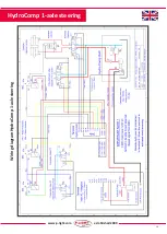
For connection of P-LIGHT HydroComp,
see separate wiring diagram
For connection of P-LIGHT HydroComp,
see separate wiring diagram


