CDV Construction Manual – Issue 3
Page 4
1
I
NTRODUCTION
The CDV (Compact Digital VFO) is a variable frequency oscillator suitable for homebrew radio
transceivers and general signal generator applications. The CDV is built on a very small PCB that
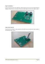
holds all parts including the rotary encoder and OLED display.
The CDV can simultaneously generate two separate signal sources. The first output has a fixed
frequency while the second is a variable frequency source using a rotary encoder as the control.
The outputs are square wave but can be conditioned by an optional add-on attenuator/low-pass
filter board.
1.1
CDV
FEATURES
Two simultaneous outputs. One variable frequency and one fixed frequency.
User programmable frequency steps.
BFO fixed output feature provides a replacement for a crystal in superhet rigs.
Simple and flexible configuration through on screen menus.
Clear and bright low current OLED display.
Very small overall size.
Simple control via a rotary encoder and two small pushbuttons.
Low power consumption.
Wide frequency range.
IF offset function.
Scanning function.
Receiver incremental Tuning (RIT).
RX/TX indication.
USB/LSB indication.
Power supply voltage display.
Automatic frequency adjustment when changing sidebands.
Calibration of frequency and voltage display.
Low power supply voltage warning.
Easy mounting using the rotary encoder shaft.
PCB comes with all SMD parts pre-loaded.
Assembly is quick and easy as most of the components are surface mount (SMD) and come pre-
installed on the PCB. There are only a handful of through-hole parts to install.
A kit of parts for the CDV including everything you need is available from
Summary of Contents for CDV
Page 1: ...CDV Construction Manual Issue 3 Page 1 CDV COMPACT DIGITAL VFO CONSTRUCTION MANUAL ...
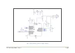
Page 8: ...CDV Construction Manual Issue 3 Page 8 Figure 1 Microcontroller and power supply schematic ...
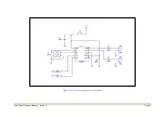
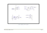
Page 9: ...CDV Construction Manual Issue 3 Page 9 Figure 2 Si5351A Clock generator schematic ...
Page 10: ...CDV Construction Manual Issue 3 Page 10 Figure 3 Display and controls schematic ...
Page 30: ...CDV Construction Manual Issue 3 Page 30 Figure 11 Attenuator filter board fitted to the CDV ...


