CDV Construction Manual – Issue 3
Page 19
IF Offset
This option is set when the CDV is used as a local oscillator in a Superhet rig. The OLED will
display the receive/transmit frequency while the actual VFO signal frequency will be offset by
an amount equal to the difference between the IF and TX frequencies.
To accommodate a wide range of applications there are two offset options available.
a)
VFO > IF.
This places the VFO frequency above the IF frequency and is the most
commonly used option.
The VFO frequency is calculated in firmware using the following equation:
VFO frequency = IF fre TX frequency.
80M example. 13.5MHz = 10MHz + 3.5MHz.
20M example. 24MHz = 10MHz + 14MHz.
b)
VFO < IF.
This places the VFO frequency below the IF frequency and is most suitable
when the TX frequency is below the IF frequency.
The VFO frequency is calculated in firmware using the following equations:
If TX frequency < IF frequency, then VFO frequency = IF frequency - TX frequency.
80M example. 6.5MHz = 10MHz - 3.5MHz.
If TX frequency > IF frequency, then VFO frequency = TX frequency - IF frequency.
20M example. 4MHz = 14MHz - 10MHz.
An
IF Offset
of
NONE
means the VFO output frequency will be the same as the displayed
frequency. This is the setting selected when the VFO is to be used as a general purpose signal
generator or with a Direct Conversion receiver.
Depending on the transceiver mixing arrangement there may be a sideband
inversion if the offset is VFO > IF.
For example, LSB generated in the balanced modulator would actually be USB at the
transmitter output, and vice versa.
If this is the case, the display can be corrected using the Set-up SIDEBAND option.
Summary of Contents for CDV
Page 1: ...CDV Construction Manual Issue 3 Page 1 CDV COMPACT DIGITAL VFO CONSTRUCTION MANUAL ...
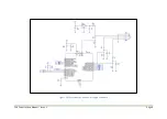
Page 8: ...CDV Construction Manual Issue 3 Page 8 Figure 1 Microcontroller and power supply schematic ...
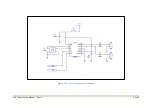
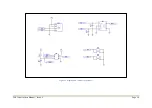
Page 9: ...CDV Construction Manual Issue 3 Page 9 Figure 2 Si5351A Clock generator schematic ...
Page 10: ...CDV Construction Manual Issue 3 Page 10 Figure 3 Display and controls schematic ...
Page 30: ...CDV Construction Manual Issue 3 Page 30 Figure 11 Attenuator filter board fitted to the CDV ...

